
XC32 Compiler for PIC32M
MPLAB XC32 C/C++ Compiler User's Guide
for PIC32M MCUs
Notice to Customers
Important:
All documentation becomes dated and this manual is no exception. Microchip tools and documentation are
constantly evolving to meet customer needs, so some actual dialogs and/or tool descriptions may differ
from those in this document. Please refer to our website (www.microchip.com) to obtain the latest
documentation available.
Documents are identified with a “DS” number. This number is located on the bottom of each page, in front
of the page number. The numbering convention for the DS number is “DSXXXXXA,” where “XXXXX” is the
document number and “A” is the revision level of the document.
For the most up-to-date information on development tools, see the MPLAB
®
X IDE online help. Select the
Help menu and then Topics, to open a list of available online help files.
© 2020 Microchip Technology Inc.
User Guide
DS50002799B-page 1

Table of Contents
Notice to Customers.......................................................................................................................................1
1. Preface....................................................................................................................................................7
1.1. Conventions Used in This Guide..................................................................................................7
1.2. Recommended Reading...............................................................................................................8
2. Compiler Overview................................................................................................................................10
2.1. Device Description..................................................................................................................... 10
2.2. Compiler Description and Documentation..................................................................................10
2.3. Compiler and Other Development Tools.....................................................................................11
3. Common C Interface............................................................................................................................. 12
3.1. Background - The Desire for Portable Code.............................................................................. 12
3.2. Using the CCI.............................................................................................................................14
3.3. ANSI Standard Refinement........................................................................................................14
3.4. ANSI Standard Extensions.........................................................................................................21
3.5. Compiler Features......................................................................................................................31
4. How To's................................................................................................................................................33
4.1. Installing and Activating the Compiler........................................................................................ 33
4.2. Invoking the Compiler.................................................................................................................34
4.3. Writing Source Code.................................................................................................................. 36
4.4. Getting My Application To Do What I Want................................................................................ 42
4.5. Understanding the Compilation Process....................................................................................45
4.6. Fixing Code That Does Not Work...............................................................................................51
5. XC32 Toolchain and MPLAB X IDE...................................................................................................... 53
5.1. MPLAB X IDE and Tools Installation.......................................................................................... 53
5.2. MPLAB X IDE Setup.................................................................................................................. 53
5.3. MPLAB X IDE Projects...............................................................................................................54
5.4. Project Setup..............................................................................................................................56
5.5. Project Example......................................................................................................................... 67
6. Command-line Driver............................................................................................................................ 69
6.1. Invoking The Compiler............................................................................................................... 69
6.2. The C Compilation Sequence.................................................................................................... 71
6.3. The C++ Compilation Sequences.............................................................................................. 73
6.4. Runtime Files............................................................................................................................. 75
6.5. Compiler Output......................................................................................................................... 78
6.6. Compiler Messages....................................................................................................................79
6.7. Driver Option Descriptions......................................................................................................... 80
7. ANSI C Standard Issues..................................................................................................................... 104
7.1. Divergence Fom the ANSI C Standard.................................................................................... 104
7.2. Extensions to the ANSI C Standard......................................................................................... 104
7.3. Implementation-Defined Behavior............................................................................................104
8. Device-Related Features.................................................................................................................... 105
XC32 Compiler for PIC32M
© 2020 Microchip Technology Inc.
User Guide
DS50002799B-page 2

8.1. Device Support.........................................................................................................................105
8.2. Device Header Files.................................................................................................................105
8.3. Stack........................................................................................................................................ 105
8.4. Configuration Bit Access.......................................................................................................... 106
8.5. ID Locations............................................................................................................................. 107
8.6. Using SFRs From C Code........................................................................................................107
9. Supported Data Types and Variables..................................................................................................110
9.1. Identifiers.................................................................................................................................. 110
9.2. Data Representation.................................................................................................................110
9.3. Integer Data Types................................................................................................................... 110
9.4. Floating-Point Data Types.........................................................................................................111
9.5. Structures and Unions.............................................................................................................. 113
9.6. Pointer Types............................................................................................................................115
9.7. Complex Data Types................................................................................................................ 117
9.8. Constant Types and Formats................................................................................................... 117
9.9. Standard Type Qualifiers.......................................................................................................... 119
9.10. Compiler-Specific Qualifiers.....................................................................................................120
9.11. Variable Attributes.................................................................................................................... 120
10. Memory Allocation and Access........................................................................................................... 124
10.1. Address Spaces....................................................................................................................... 124
10.2. Variables in Data Memory........................................................................................................ 124
10.3. Auto Variable Allocation and Access........................................................................................126
10.4. Variables in Program Memory..................................................................................................127
10.5. Variable in Registers................................................................................................................ 128
10.6. Application-Defined Memory Regions......................................................................................128
10.7. Dynamic Memory Allocation.....................................................................................................131
10.8. Memory Models........................................................................................................................132
11. Fixed-Point Arithmetic Support........................................................................................................... 133
11.1. Enabling Fixed-Point Arithmetic Support..................................................................................133
11.2. Data Types............................................................................................................................... 133
11.3. External Definitions.................................................................................................................. 135
11.4. SIMD Variables.........................................................................................................................135
11.5. Accessing Elements in SIMD Variables................................................................................... 136
11.6. Array Alignment and Data Layout............................................................................................ 138
11.7. C Operators..............................................................................................................................138
11.8. Operations on SIMD Variables.................................................................................................139
11.9. DSP Built-In Functions............................................................................................................. 140
11.10. DSP Control Register............................................................................................................... 140
11.11. Using Accumulators................................................................................................................. 140
11.12. Mixed-Mode Operations........................................................................................................... 141
11.13. Auto-Vectorization to SIMD...................................................................................................... 142
11.14. FIR Filter Example Project....................................................................................................... 142
12. Operators and Statements.................................................................................................................. 145
12.1. Integral Promotion....................................................................................................................145
12.2. Type References...................................................................................................................... 146
XC32 Compiler for PIC32M
© 2020 Microchip Technology Inc.
User Guide
DS50002799B-page 3

12.3. Labels as Values...................................................................................................................... 146
12.4. Conditional Operator Operands............................................................................................... 147
12.5. Case Ranges............................................................................................................................147
13. Register Usage................................................................................................................................... 149
13.1. Register Usage.........................................................................................................................149
13.2. Register Conventions...............................................................................................................149
14. Functions.............................................................................................................................................151
14.1. Writing Functions......................................................................................................................151
14.2. Function Attributes and Specifiers............................................................................................151
14.3. Allocation of Function Code..................................................................................................... 155
14.4. Changing the Default Function Allocation................................................................................ 156
14.5. Function Size Limits................................................................................................................. 156
14.6. Function Parameters................................................................................................................156
14.7. Function Return Values............................................................................................................158
14.8. Calling Functions......................................................................................................................159
14.9. Inline Functions........................................................................................................................ 159
15. Interrupts............................................................................................................................................. 161
15.1. Interrupt Operation................................................................................................................... 161
15.2. Writing an Interrupt Service Routine........................................................................................ 161
15.3. Associating a Handler Function with an Exception Vector....................................................... 165
15.4. Exception Handlers.................................................................................................................. 166
15.5. Interrupt Service Routine Context Switching............................................................................167
15.6. Latency.....................................................................................................................................168
15.7. Nesting Interrupts.....................................................................................................................168
15.8. Enabling/Disabling Interrupts................................................................................................... 168
15.9. ISR Considerations.................................................................................................................. 168
16. Main, Runtime Start-up and Reset......................................................................................................169
16.1. The Main Function....................................................................................................................169
16.2. Runtime Start-Up Code............................................................................................................169
16.3. The On Reset Routine..............................................................................................................180
17. Library Routines.................................................................................................................................. 181
17.1. Using Library Routines.............................................................................................................181
18. Mixing C/C++ and Assembly Language..............................................................................................182
18.1. Mixing Assembly Language and C Variables and Functions................................................... 182
18.2. Using Inline Assembly Language.............................................................................................184
18.3. Predefined Macros................................................................................................................... 186
19. Optimizations...................................................................................................................................... 189
20. Preprocessing..................................................................................................................................... 190
20.1. C/C++ Language Comments....................................................................................................190
20.2. Preprocessor Directives........................................................................................................... 190
20.3. Pragma Directives....................................................................................................................191
20.4. Predefined Macros................................................................................................................... 192
XC32 Compiler for PIC32M
© 2020 Microchip Technology Inc.
User Guide
DS50002799B-page 4

21. Linking Programs................................................................................................................................ 196
21.1. Replacing Library Symbols.......................................................................................................196
21.2. Linker-Defined Symbols........................................................................................................... 196
21.3. Default Linker Script.................................................................................................................196
22. Embedded Compiler Compatibility Mode............................................................................................210
22.1. Compiling in Compatibility Mode..............................................................................................210
22.2. Syntax Compatibility.................................................................................................................210
22.3. Data Type................................................................................................................................. 211
22.4. Operator................................................................................................................................... 211
22.5. Extended Keywords..................................................................................................................211
22.6. Intrinsic Functions.................................................................................................................... 213
22.7. Pragmas...................................................................................................................................213
23. Implementation-Defined Behavior.......................................................................................................215
23.1. Overview.................................................................................................................................. 215
23.2. Translation................................................................................................................................215
23.3. Environment............................................................................................................................. 215
23.4. Identifiers..................................................................................................................................216
23.5. Characters................................................................................................................................216
23.6. Integers.................................................................................................................................... 217
23.7. Floating-Point........................................................................................................................... 217
23.8. Arrays and Pointers..................................................................................................................218
23.9. Hints......................................................................................................................................... 219
23.10. Structures, Unions, Enumerations, and Bit Fields....................................................................219
23.11. Qualifiers.................................................................................................................................. 220
23.12. Declarators...............................................................................................................................220
23.13. Statements...............................................................................................................................220
23.14. Pre-Processing Directives........................................................................................................220
23.15. Library Functions......................................................................................................................221
23.16. Architecture..............................................................................................................................225
24. Deprecated Features.......................................................................................................................... 226
24.1. Variables in Specified Registers...............................................................................................226
24.2. Defining Global Register Variables...........................................................................................226
24.3. Specifying Registers for Local Variables..................................................................................227
25. Built-In Functions................................................................................................................................ 228
26. Built-In Function Descriptions............................................................................................................. 229
26.1. __builtin_bcc0(rn,sel,clr).......................................................................................................... 229
26.2. __builtin_bsc0(rn,sel,set)......................................................................................................... 229
26.3. __builtin_bcsc0(rn,sel,clr,set)...................................................................................................230
26.4. __builtin_clz(x)......................................................................................................................... 230
26.5. __builtin_ctz(x)......................................................................................................................... 231
26.6. __builtin_mips_cache(op,addr)................................................................................................ 231
26.7. __builtin_mxc0(rn,sel,val).........................................................................................................232
26.8. __builtin_set_isr_state(unsigned int)........................................................................................232
26.9. __builtin_software_breakpoint(void).........................................................................................232
XC32 Compiler for PIC32M
© 2020 Microchip Technology Inc.
User Guide
DS50002799B-page 5

26.10. unsigned long__builtin_section_begin(quoted-section-name).................................................233
26.11. unsigned long __builtin_section_end(quoted-section-name)................................................... 233
26.12. unsigned long __builtin_section_size(quoted-section-name).................................................. 234
26.13. unsigned int __builtin_get_isr_state(void)................................................................................234
27. Built-In DSP Functions........................................................................................................................ 236
28. ASCII Character Set............................................................................................................................242
29. Document Revision History.................................................................................................................243
The Microchip Website...............................................................................................................................244
Product Change Notification Service..........................................................................................................244
Customer Support...................................................................................................................................... 244
Microchip Devices Code Protection Feature.............................................................................................. 244
Legal Notice............................................................................................................................................... 244
Trademarks................................................................................................................................................ 245
Quality Management System..................................................................................................................... 245
Worldwide Sales and Service.....................................................................................................................246
XC32 Compiler for PIC32M
© 2020 Microchip Technology Inc.
User Guide
DS50002799B-page 6
1. Preface
MPLAB
®
XC32 C/C++ Compiler for PICM MCUs documentation and support information is discussed in this section.
1.1 Conventions Used in This Guide
The following conventions may appear in this documentation:
Table 1-1. Documentation Conventions
Description Represents Examples
Arial font:
Italic characters Referenced books MPLAB
®
IDE User’s Guide
Emphasized text ...is the only compiler...
Initial caps A window the Output window
A dialog the Settings dialog
A menu selection select Enable Programmer
Quotes A field name in a window or dialog “Save project before build”
Underlined, italic text with right
angle bracket
A menu path File>Save
Bold characters A dialog button Click OK
A tab Click the Power tab
N‘Rnnnn A number in verilog format, where
N is the total number of digits, R is
the radix and n is a digit.
4‘b0010, 2‘hF1
Text in angle brackets < > A key on the keyboard Press <Enter>, <F1>
Courier New font:
Plain Courier New Sample source code
#define START
Filenames
autoexec.bat
File paths
c:\mcc18\h
Keywords
_asm, _endasm, static
Command-line options
-Opa+, -Opa-
Bit values
0, 1
Constants
0xFF, ‘A’
Italic Courier New A variable argument file.o, where file can be any valid
filename
Square brackets [ ] Optional arguments
mcc18 [options] file [options]
Curly brackets and pipe
character: { | }
Choice of mutually exclusive
arguments; an OR selection
errorlevel {0|1}
XC32 Compiler for PIC32M
Preface
© 2020 Microchip Technology Inc.
User Guide
DS50002799B-page 7

...........continued
Description Represents Examples
Ellipses... Replaces repeated text
var_name [, var_name...]
Represents code supplied by user
void main (void)
{ ...
}
1.2 Recommended Reading
The MPLAB
®
XC32 language toolsuite for PIC32 MCUs consists of a C compilation driver (xc32-gcc), a C++
compilation driver (xc32-g++), an assembler (xc32-as), a linker (xc32-ld), and an archiver/librarian (xc32-ar).
This document describes how to use the MPLAB XC32 C/C++ Compiler. Other useful documents are listed below.
The following Microchip documents are available and recommended as supplemental reference resources.
Release Notes (Readme Files)
For the latest information on Microchip tools, read the associated Release Notes (HTML files) included with the
software.
MPLAB
®
XC32 Assembler, Linker and Utilities User’s Guide (DS50002186)
A guide to using the 32-bit assembler, object linker, object archiver/librarian and various utilities.
32-Bit Language Tools Libraries (DS50001685)
Lists all library functions provided with the MPLAB XC32 C/C++ Compiler with detailed descriptions of their use.
Dinkum Compleat Libraries
The Dinkum Compleat Libraries are organized into a number of headers – files that you include in your program to
declare or define library facilities. A link to the Dinkum libraries is available in the MPLAB X IDE application, on the
My MPLAB X IDE tab, References & Featured Links section.
PIC32 Configuration Settings
Lists the Configuration Bit settings for the Microchip PIC32 devices supported by the #pragma config of the
MPLAB XC32 C/C++ Compiler.
Device-Specific Documentation
The Microchip website contains many documents that describe 32-bit device functions and features. Among these
are:
• Individual and family data sheets
• Family reference manuals
• Programmer’s reference manuals
C Standards Information
American National Standard for Information Systems – Programming Language – C. American National Standards
Institute (ANSI), 11 West 42nd. Street, New York, New York, 10036.
This standard specifies the form and establishes the interpretation of programs expressed in the programming
language C. Its purpose is to promote portability, reliability, maintainability and efficient execution of C language
programs on a variety of computing systems.
C++ Standards Information
Stroustrup, Bjarne, C++ Programming Language: Special Edition, 3rd Edition. Addison-Wesley Professional;
Indianapolis, Indiana, 46240.
ISO/IEC 14882 C++ Standard. The ISO C++ Standard is standardized by ISO (The International Standards
Organization) in collaboration with ANSI (The American National Standards Institute), BSI (The British Standards
Institute) and DIN (The German national standards organization).
XC32 Compiler for PIC32M
Preface
© 2020 Microchip Technology Inc.
User Guide
DS50002799B-page 8

This standard specifies the form and establishes the interpretation of programs expressed in the programming
language C++. Its purpose is to promote portability, reliability, maintainability and efficient execution of C++ language
programs on a variety of computing systems.
C Reference Manuals
Harbison, Samuel P. and Steele, Guy L., C A Reference Manual, Fourth Edition, Prentice-Hall, Englewood Cliffs, N.J.
07632.
Kernighan, Brian W. and Ritchie, Dennis M., The C Programming Language, Second Edition. Prentice Hall,
Englewood Cliffs, N.J. 07632.
Kochan, Steven G., Programming In ANSI C, Revised Edition. Hayden Books, Indianapolis, Indiana 46268.
Plauger, P.J., The Standard C Library, Prentice-Hall, Englewood Cliffs, N.J. 07632.
Van Sickle, Ted., Programming Microcontrollers in C, First Edition. LLH Technology Publishing, Eagle Rock, Virginia
24085.
GCC Documents
http://gcc.gnu.org/onlinedocs/
http://sourceware.org/binutils/
XC32 Compiler for PIC32M
Preface
© 2020 Microchip Technology Inc.
User Guide
DS50002799B-page 9

2. Compiler Overview
The MPLAB
®
XC32 C/C++ Compiler for PIC32M MCUs is defined and described in this section.
2.1 Device Description
The MPLAB XC32 C/C++ Compiler fully supports most Microchip PIC32M and MEC 14 devices.
2.2 Compiler Description and Documentation
The MPLAB XC32 C/C++ Compiler is a full-featured, optimizing compiler that translates standard ANSI C programs
into 32-bit device assembly language source. The toolchain supports both the PIC32M microcontroller family. The
compiler also supports many command-line options and language extensions that allow full access to the 32-bit
device hardware capabilities, and affords fine control of the compiler code generator.
The compiler is a port of the GCC compiler from the Free Software Foundation.
The compiler is available for several popular operating systems, including 32- and 64-bit Windows
®
, Linux
®
and Mac
OS
®
X.
The compiler can run in Free or PRO operating mode. The PRO operating mode is a licensed mode and requires an
activation key and Internet connectivity to enable it. Free mode is available for unlicensed customers. The basic
compiler operation, supported devices and available memory are identical across all modes. The modes only differ in
the level of optimization employed by the compiler.
2.2.1 Conventions
Throughout this manual, the term “the compiler” is often used. It can refer to either all or some subset of the collection
of applications that form the MPLAB XC32 C/C++ Compiler. Often it is not important to know, for example, whether
an action is performed by the parser or code generator application and it is sufficient to say it was performed by “the
compiler.”
It is also reasonable for “the compiler” to refer to the command-line driver (or just driver) as this is the application that
is always executed to invoke the compilation process. The driver for the MPLAB XC32 C/C++ Compiler package is
called xc32-gcc. The driver for the C/ASM projects is also xc32-gcc. The driver for C/C++/ASM projects is xc32-
g++. The drivers and their options are discussed in 6.7 Driver Option Descriptions. Following this view, “compiler
options” should be considered command-line driver options, unless otherwise specified in this manual.
Similarly “compilation” refers to all, or some part of, the steps involved in generating source code into an executable
binary image.
2.2.2 ANSI C Standards
The compiler is a fully validated compiler that conforms to the ANSI C standard as defined by the ANSI specification
(ANSI x3.159-1989) and described in Kernighan and Ritchie’s The C Programming Language (second edition). The
ANSI standard includes extensions to the original C definition that are now standard features of the language. These
extensions enhance portability and offer increased capability. In addition, language extensions for PIC32 MCU
embedded-control applications are included.
2.2.3 Optimization
The compiler uses a set of sophisticated optimization passes that employ many advanced techniques for generating
efficient, compact code from C/C++ source. The optimization passes include high-level optimizations that are
applicable to any C/C++ code, as well as PIC32 MCU-specific optimizations that take advantage of the particular
features of the device architecture.
For more on optimizations, see 19. Optimizations.
2.2.4 ANSI Standard Library Support
The compiler is distributed with a complete ANSI C standard library. All library functions have been validated and
conform to the ANSI C library standard. The library includes functions for string manipulation, dynamic memory
XC32 Compiler for PIC32M
Compiler Overview
© 2020 Microchip Technology Inc.
User Guide
DS50002799B-page 10

allocation, data conversion, timekeeping and math functions (trigonometric, exponential and hyperbolic). The
standard I/O functions for file handling are also included, and, as distributed, they support full access to the host file
system using the command-line simulator. The fully functional source code for the low-level file I/O functions is
provided in the compiler distribution, and may be used as a starting point for applications that require this capability.
2.2.5 ISO/IEC C++ Standard
The compiler is distributed with the 2003 Standard C++ Library.
Note: Do not specify an MPLAB XC32 system include directory (for example, /pic32mx/include/) in your
project properties.The xc32-gcc compilation drivers automatically select the XC libc and their respective include-file
directory for you. The xc32-g++ compilation drivers automatically select the Dinkumware libc and their respective
include-file directory for you. The Dinkum C libraries can only be used with the C++ compiler. Manually adding a
system include file path may disrupt this mechanism and cause the incorrect libc include files to be compiled into your
project, causing a conflict between the include files and the library. Note that adding a system include path to your
project properties has never been a recommended practice.
2.2.6 Compiler Driver
The compiler includes a powerful command-line driver program. Using the driver program, application programs can
be compiled, assembled and linked in a single step.
2.2.7 Documentation
This version of the C compiler is supported under MPLAB X IDE v5.05 or higher is required.
2.3 Compiler and Other Development Tools
The compiler works with many other Microchip tools including:
• MPLAB XC32 assembler and linker - see the “MPLAB
®
XC32 Assembler, Linker and Utilities User’s Guide”
(DS50002186).
• MPLAB X IDE (v5.05 or higher).
• The MPLAB Simulator.
• All Microchip debug tools and programmers.
• Demo boards and starter kits that support 32-bit devices.
XC32 Compiler for PIC32M
Compiler Overview
© 2020 Microchip Technology Inc.
User Guide
DS50002799B-page 11

3. Common C Interface
The Common C Interface (CCI) is available with all MPLAB XC C compilers and is designed to enhance code
portability between these compilers. For example, CCI-conforming code would make it easier to port from a PIC18
MCU using the MPLAB XC8 C compiler to a PIC32 MCU using the MPLAB XC32 C/C++ Compiler.
The CCI assumes that your source code already conforms to the ANSI Standard. If you intend to use the CCI, it is
your responsibility to write code that conforms. Legacy projects will need to be migrated to achieve conformance. A
compiler option must also be set to ensure that the operation of the compiler is consistent with the interface when the
project is built.
3.1 Background - The Desire for Portable Code
All programmers want to write portable source code.
Portability means that the same source code can be compiled and run in a different execution environment than that
for which it was written. Rarely can code be one hundred percent portable, but the more tolerant it is to change, the
less time and effort it takes to have it running in a new environment.
Embedded engineers typically think of code portability as being across target devices, but this is only part of the
situation. The same code could be compiled for the same target but with a different compiler. Differences between
those compilers might lead to the code failing at compile time or runtime, so this must be considered as well.
You can only write code for one target device and only use one brand of compiler; but if there is no regulation of the
compiler’s operation, simply updating your compiler version can change your code’s behavior.
Code must be portable across targets, tools, and time to be truly flexible.
Clearly, this portability cannot be achieved by the programmer alone, since the compiler vendors can base their
products on different technologies, implement different features and code syntax, or improve the way their product
works. Many a great compiler optimization has broken many an unsuspecting project.
Standards for the C language have been developed to ensure that change is managed and code is more portable.
The American National Standards Institute (ANSI) publishes standards for many disciplines, including programming
languages. The ANSI C Standard is a universally adopted standard for the C programming language.
3.1.1 The ANSI Standard
The ANSI C Standard has to reconcile two opposing goals: freedom for compilers vendors to target new devices and
improve code generation, with the known functional operation of source code for programmers. If both goals can be
met, source code can be made portable.
The standard is implemented as a set of rules which detail not only the syntax that a conforming C program must
follow, but the semantic rules by which that program will be interpreted. Thus, for a compiler to conform to the
standard, it must ensure that a conforming C program functions as described by the standard.
The standard describes implementation, the set of tools and the runtime environment on which the code will run. If
any of these change, for example, you build for, and run on, a different target device, or if you update the version of
the compiler you use to build, then you are using a different implementation.
The standard uses the term behavior to mean the external appearance or action of the program. It has nothing to do
with how a program is encoded.
Since the standard is trying to achieve goals that could be construed as conflicting, some specifications appear
somewhat vague. For example, the standard states that an int type must be able to hold at least a 16-bit value, but
it does not go as far as saying what the size of an int actually is; and the action of right-shifting a signed integer can
produce different results on different implementations; yet, these different results are still ANSI C compliant.
If the standard is too strict, device architectures cannot allow the compiler to conform (see following note). But, if it is
too weak, programmers would see wildly differing results within different compilers and architectures, and the
standard would lose its effectiveness.
XC32 Compiler for PIC32M
Common C Interface
© 2020 Microchip Technology Inc.
User Guide
DS50002799B-page 12

Note: For example, the mid-range PIC
®
microcontrollers do not have a data stack. Because a compiler targeting this
device cannot implement recursion, it (strictly speaking) cannot conform to the ANSI C Standard. This example
illustrates a situation in which the standard is too strict for mid-range devices and tools.
The standard organizes source code whose behavior is not fully defined into groups that include the following
behaviors:
Implementation-defined behavior This is unspecified behavior in which each implementation
documents how the choice is made.
Unspecified behavior The standard provides two or more possibilities and imposes no
further requirements on which possibility is chosen in any
particular instance.
Undefined behavior This is behavior for which the standard imposes no requirements.
Code that strictly conforms to the standard does not produce output that is dependent on any unspecified, undefined,
or implementation-defined behavior. The size of an int, which was used as an example earlier, falls into the
category of behavior that is defined by implementation. That is to say, the size of an int is defined by which compiler
is being used, how that compiler is being used, and the device that is being targeted.
All the MPLAB XC compilers conform to the ANSI X3.159-1989 Standard for programming languages (with the
exception of the MPLAB XC8 compiler’s inability to allow recursion, as mentioned in the footnote). This is commonly
called the C89 Standard. Some features from the later standard, C99, are also supported.
For freestanding implementations (or for what are typically call embedded applications), the standard allows non-
standard extensions to the language, but obviously does not enforce how they are specified or how they work. When
working so closely to the device hardware, a programmer needs a means of specifying device setup and interrupts,
as well as utilizing the often complex world of small-device memory architectures. This cannot be offered by the
standard in a consistent way.
While the ANSI C Standard provides a mutual understanding for programmers and compiler vendors, programmers
need to consider the implementation-defined behavior of their tools and the probability that they may need to use
extensions to the C language that are non-standard. Both of these circumstances can have an impact on code
portability.
3.1.2 The Common C Interface
The Common C Interface (CCI) supplements the ANSI C Standard and makes it easier for programmers to achieve
consistent outcomes on all Microchip devices when using any of the MPLAB XC C compilers.
It delivers the following improvements, all designed with portability in mind.
Refinement of the ANSI C Standard The CCI documents specific behavior for some code in which actions
are implementation-defined behavior under the ANSI C Standard.
For example, the result of right-shifting a signed integer is fully
defined by the CCI. Note that many implementation-defined items
that closely couple with device characteristics, such as the size of an
int, are not defined by the CCI.
Consistent syntax for non-standard
extensions
The CCI non-standard extensions are mostly implemented using
keywords with a uniform syntax. They replace keywords, macros and
attributes that are the native compiler implementation. The
interpretation of the keyword can differ across each compiler, and
any arguments to the keywords can be device specific.
Coding guidelines The CCI can indicate advice on how code should be written so that it
can be ported to other devices or compilers. While you may choose
not to follow the advice, it will not conform to the CCI.
XC32 Compiler for PIC32M
Common C Interface
© 2020 Microchip Technology Inc.
User Guide
DS50002799B-page 13

3.2 Using the CCI
The CCI allows enhanced portability by refining implementation-defined behavior and standardizing the syntax for
extensions to the language.
The CCI is something you choose to follow and put into effect, thus it is relevant for new projects, although you can
choose to modify existing projects so they conform.
For your project to conform to the CCI, you must do the following things.
• Enable the CCI
Select the MPLAB X IDE widget
Use CCI Syntax in your project, or use the command-line option that is
equivalent.
• Include <xc.h> in every module
Some CCI features are only enabled if this header is seen by the compiler.
• Ensure ANSI compliance
Code that does not conform to the ANSI C Standard does not conform to the CCI.
• Observe refinements to ANSI by the CCI
Some ANSI implementation-defined behavior is defined explicitly by the CCI.
• Use the CCI extensions to the language
Use the CCI extensions rather than the native language extensions.
The next sections detail specific items associated with the CCI. These items are segregated into those that refine the
standard, those that deal with the ANSI C Standard extensions, and other miscellaneous compiler options and usage.
Guidelines are indicated with these items.
If any implementation-defined behavior or any non-standard extension is not discussed in this document, then it is not
part of the CCI. For example, GCC case ranges, label addresses and 24-bit short long types are not part of the
CCI. Programs which use these features do not conform to the CCI. The compiler may issue a warning or error to
indicate a non-CCI feature has been used and the CCI is enabled.
3.3 ANSI Standard Refinement
The following topics describe how the CCI refines the implementation-defined behaviors outlined in the ANSI C
Standard.
3.3.1 Source File Encoding
Under the CCI, a source file must be written using characters from the 7-bit ASCII set. Lines can be terminated using
a line feed (\n) or carriage return (\r) that is immediately followed by a line feed. Escaped characters can be used
in character constants or string literals to represent extended characters that are not in the basic character set.
Example
The following shows a string constant being defined that uses escaped characters.
const char myName[] = "Bj\370rk\n";
Differences
All compilers have used this character set.
Migration to the CCI
No action required.
3.3.2 The Prototype for main
The prototype for the main() function is:
int main(void);
Example
XC32 Compiler for PIC32M
Common C Interface
© 2020 Microchip Technology Inc.
User Guide
DS50002799B-page 14

The following shows an example of how main() might be defined:
int main(void)
{
while(1)
process();
}
Differences
The 8-bit compilers used a void return type for this function.
Migration to the CCI
Each program has one definition for the main() function. Confirm the return type for main() in all projects
previously compiled for 8-bit targets.
3.3.3 Header File Specification
Header file specifications that use directory separators do not conform to the CCI.
Example
The following example shows two conforming include directives.
#include <usb_main.h>
#include "global.h"
Differences
Header file specifications that use directory separators have been allowed in previous versions of all compilers.
Compatibility problems arose when Windows-style separators “\” were used and the code was compiled under other
host operating systems. Under the CCI, no directory separators should be used.
Migration to the CCI
Any #include directives that use directory separators in the header file specifications should be changed. Remove
all but the header file name in the directive. Add the directory path to the compiler’s include search path or MPLAB X
IDE equivalent. This will force the compiler to search the directories specified with this option.
For example, the following code:
#include <inc/lcd.h>
should be changed to:
#include <lcd.h>
and the path to the inc directory added to the compiler’s header search path in your MPLAB X IDE project
properties, or on the command-line as follows:
-Ilcd
3.3.4 Include Search Paths
When you include a header file under the CCI, the file should be discoverable in the paths searched by the compiler
that are detailed below.
Header files specified in angle bracket delimiters < > should be discoverable in the search paths that are specified
by -I options (or the equivalent MPLAB X IDE option), or in the standard compiler include directories. The -I
options are searched in the order in which they are specified.
Header files specified in quote characters " " should be discoverable in the current working directory or in the same
directories that are searched when the header files are specified in angle bracket delimiters (as above). In the case of
an MPLAB X project, the current working directory is the directory in which the C source file is located. If
unsuccessful, the search paths should be to the same directories searched when the header file is specified in angle
bracket delimiters.
Any other options to specify search paths for header files do not conform to the CCI.
XC32 Compiler for PIC32M
Common C Interface
© 2020 Microchip Technology Inc.
User Guide
DS50002799B-page 15

Example
If including a header file, as in the following directive:
#include "myGlobals.h"
the header file should be locatable in the current working directory, or the paths specified by any -I options, or the
standard compiler directories. A header file being located elsewhere does not conform to the CCI.
Differences
The compiler operation under the CCI is not changed. This is purely a coding guideline.
Migration to the CCI
Remove any option that specifies header file search paths other than the -I option (or the equivalent MPLAB X IDE
option), and use the -I option in place of this. Ensure the header file can be found in the directories specified in this
section.
3.3.5 The Number of Significant Initial Characters in an Identifier
At least the first 255 characters in an identifier (internal and external) are significant. This extends upon the
requirement of the ANSI C Standard that states a lower number of significant characters are used to identify an
object.
Example
The following example shows two poorly named variables, but names which are considered unique under the CCI.
int stateOfPortBWhenTheOperatorHasSelectedAutomaticModeAndMotorIsRunningFast;
int stateOfPortBWhenTheOperatorHasSelectedAutomaticModeAndMotorIsRunningSlow;
Differences
Former 8-bit compilers used 31 significant characters by default, but an option allowed this to be extended.
The 16- and 32-bit compilers did not impose a limit on the number of significant characters.
Migration to the CCI
No action required. You can take advantage of the less restrictive naming scheme.
3.3.6 Sizes of Types
The sizes of the basic C types, for example char, int and long, are not fully defined by the CCI. These types, by
design, reflect the size of registers and other architectural features in the target device. They allow the device to
efficiently access objects of this type. The ANSI C Standard does, however, indicate minimum requirements for these
types, as specified in <limits.h>.
If you need fixed-size types in your project, use the types defined in <stdint.h>, for example, uint8_t or
int16_t. These types are consistently defined across all XC compilers, even outside of the CCI.
Essentially, the C language offers a choice of two groups of types: those that offer sizes and formats that are tailored
to the device you are using; or those that have a fixed size, regardless of the target.
Example
The following example shows the definition of a variable, native, whose size will allow efficient access on the target
device; and a variable, fixed, whose size is clearly indicated and remains fixed, even though it may not allow
efficient access on every device.
int native;
int16_t fixed;
Differences
This is consistent with previous types implemented by the compiler.
Migration to the CCI
XC32 Compiler for PIC32M
Common C Interface
© 2020 Microchip Technology Inc.
User Guide
DS50002799B-page 16

If you require a C type that has a fixed size, regardless of the target device, use one of the types defined by
<stdint.h>.
3.3.7 Plain char Types
The type of a plain char is unsigned char. It is generally recommended that all definitions for the char type
explicitly state the signedness of the object.
Example
The following example
char foobar;
defines an unsigned char object called foobar.
Differences
The 8-bit compilers have always treated plain char as an unsigned type.
The 16- and 32-bit compilers used signed char as the default plain char type. The -funsigned-char option on
those compilers changed the default type to be unsigned char.
Migration to the CCI
Any definition of an object defined as a plain char and using the 16- or 32-bit compilers needs review. Any plain
char that was intended to be a signed quantity should be replaced with an explicit definition, for example.
signed char foobar;
You can use the -funsigned-char option on MPLAB XC16 and XC32 to change the type of plain char, but since
this option is not supported on MPLAB XC8, the code is not strictly conforming.
3.3.8 Signed Integer Representation
The value of a signed integer is determined by taking the two’s complement of the integer.
Example
The following shows a variable, test, that is assigned the value -28 decimal.
signed char test = 0xE4;
Differences
All compilers have represented signed integers in the way described in this section.
Migration to the CCI
No action required.
3.3.9 Integer Conversion
When converting an integer type to a signed integer of insufficient size, the original value is truncated from the most-
significant bit to accommodate the target size.
Example
The following shows an assignment of a value that is truncated.
signed char destination;
unsigned int source = 0x12FE;
destination = source;
Under the CCI, the value of destination after the alignment is -2 (that is, the bit pattern 0xFE).
Differences
All compilers have performed integer conversion in an identical fashion to that described in this section.
Migration to the CCI
No action required.
XC32 Compiler for PIC32M
Common C Interface
© 2020 Microchip Technology Inc.
User Guide
DS50002799B-page 17

3.3.10 Bitwise Operations on Signed Values
Bitwise operations on signed values act on the two’s complement representation, including the sign bit. See also
3.3.11 Right-Shifting Signed Values.
Example
The following shows an example of a negative quantity involved in a bitwise AND operation.
signed char output, input = -13;
output = input & 0x7E;
Under the CCI, the value of output after the assignment is 0x72.
Differences
All compilers have performed bitwise operations in an identical fashion to that described in this section.
Migration to the CCI
No action required.
3.3.11 Right-Shifting Signed Values
Right-shifting a signed value will involve sign extension. This will preserve the sign of the original value.
Example
The following example shows a negative quantity involved in a right-shift operation.
signed char output, input = -13;
output = input >> 3;
Under the CCI, the value of output after the assignment is -2 (that is, the bit pattern 0xFE).
Differences
All compilers have performed right-shifting as described in this section.
Migration to the CCI
No action required.
3.3.12 Conversion of Union Member Accessed Using Member with Different Type
If a union defines several members of different types and you use one member identifier to try to access the contents
of another (whether any conversion is applied to the result) is implementation-defined behavior in the standard. In the
CCI, no conversion is applied and the bytes of the union object are interpreted as an object of the type of the member
being accessed, without regard for alignment or other possible invalid conditions.
Example
The following shows an example of a union defining several members.
union {
signed char code;
unsigned int data;
float offset;
} foobar;
Code that attempts to extract offset by reading data is not guaranteed to read the correct value.
float result;
result = foobbar.data;
Differences
All compilers have not converted union members accessed via other members.
Migration to the CCI
No action required.
XC32 Compiler for PIC32M
Common C Interface
© 2020 Microchip Technology Inc.
User Guide
DS50002799B-page 18

3.3.13 Default Bit-field int Type
The type of a bit-field specified as a plain int is identical to that of one defined using unsigned int. This is quite
different from other objects where the types int, signed and signed int are synonymous. It is recommended
that the signedness of the bit-field be explicitly stated in all bit-field definitions.
Example
The following shows an example of a structure tag containing bit-fields that are unsigned integers and with the size
specified.
struct OUTPUTS {
int direction :1;
int parity :3;
int value :4;
};
Differences
The 8-bit compilers have previously issued a warning if type int was used for bit-fields, but would implement the bit-
field with an unsigned int type.
The 16- and 32-bit compilers have implemented bit-fields defined using int as having a signed int type, unless
the option -funsigned-bitfields was specified.
Migration to the CCI
Any code that defines a bit-field with the plain int type should be reviewed. If the intention was for these to be
signed quantities, then the type of these should be changed to signed int. In the following example:
struct WAYPT {
int log :3;
int direction :4;
};
the bit-field type should be changed to signed int, as in:
struct WAYPT {
signed int log :3;
signed int direction :4;
};
3.3.14 Bit-Fields Straddling a Storage Unit Boundary
The standard indicates that implementations can determine whether bit-fields cross a storage unit boundary. In the
CCI, bit-fields do not straddle a storage unit boundary; a new storage unit is allocated to the structure, and padding
bits fill the gap.
Note that the size of a storage unit differs with each compiler, as this is based on the size of the base data type (for
example, int) from which the bit-field type is derived. On 8-bit compilers this unit is 8-bits in size; for 16-bit
compilers, it is 16 bits; and for 32-bit compilers, it is 32 bits in size.
Example
The following shows a structure containing bit-fields being defined.
struct {
unsigned first : 6;
unsigned second :6;
} order;
Under the CCI and using MPLAB XC8, the storage allocation unit is byte sized. The bit-field second is allocated a
new storage unit since there are only 2 bits remaining in the first storage unit in which first is allocated. The size of
this structure, order, is 2 bytes.
Differences
This allocation is identical with that used by all previous compilers.
XC32 Compiler for PIC32M
Common C Interface
© 2020 Microchip Technology Inc.
User Guide
DS50002799B-page 19

Migration to the CCI
No action required.
3.3.15 The Allocation Order of Bit-Field
The memory ordering of bit-fields into their storage unit is not specified by the ANSI C Standard. In the CCI, the first
bit defined is the least significant bit (LSb) of the storage unit in which it is allocated.
Example
The following shows a structure containing bit-fields being defined.
struct {
unsigned lo : 1;
unsigned mid :6;
unsigned hi : 1;
} foo;
The bit-field lo is assigned the least significant bit of the storage unit assigned to the structure foo. The bit-field mid
is assigned the next 6 least significant bits, and hi, the most significant bit of that same storage unit byte.
Differences
This is identical with the previous operation of all compilers.
Migration to the CCI
No action required.
3.3.16 The NULL Macro
The NULL macro is defined by <stddef.h>; however, its definition is implementation-defined behavior. Under the
CCI, the definition of NULL is the expression (0).
Example
The following shows a pointer being assigned a null pointer constant via the NULL macro.
int * ip = NULL;
The value of NULL, (0), is implicitly converted to the destination type.
Differences
The 32-bit compilers previously assigned NULL the expression ((void *)0).
Migration to the CCI
No action required.
3.3.17 Floating-Point Sizes
Under the CCI, floating-point types must not be smaller than 32 bits in size.
Example
The following shows the definition for outY, which is at least 32-bit in size.
float outY;
Differences
The 8-bit compilers have allowed the use of 24-bit float and double types.
Migration to the CCI
When using 8-bit compilers, the float and double type will automatically be made 32 bits in size once the CCI
mode is enabled. Review any source code that may have assumed a float or double type and may have been 24
bits in size.
No migration is required for other compilers.
XC32 Compiler for PIC32M
Common C Interface
© 2020 Microchip Technology Inc.
User Guide
DS50002799B-page 20

3.4 ANSI Standard Extensions
The following topics describe how the CCI provides device-specific extensions to the standard.
3.4.1 Generic Header File
A single header file <xc.h> must be used to declare all compiler- and device-specific types and SFRs. You must
include this file into every module to conform with the CCI. Some CCI definitions depend on this header being seen.
Example
The following shows this header file being included, thus allowing conformance with the CCI, as well as allowing
access to SFRs.
#include <xc.h>
Differences
Some 8-bit compilers used <htc.h> as the equivalent header. Previous versions of the 16- and 32-bit compilers
used a variety of headers to do the same job.
Migration to the CCI
Change:
#include <htc.h>
previously used in 8-bit compiler code, or family-specific header files, for example, from:
#include <p32xxxx.h>
#include <p30fxxxx.h>
#include <p33Fxxxx.h>
#include <p24Fxxxx.h>
#include "p30f6014.h"
to:
#include <xc.h>
3.4.2 Absolute Addressing
Variables and functions can be placed at an absolute address by using the __at() construct. Stack-based (auto
and parameter) variables cannot use the __at() specifier.
Example
The following shows two variables and a function being made absolute.
int scanMode __at(0x200);
const char keys[] __at(123) = { ’r’, ’s’, ’u’, ’d’};
}
Differences
The 8-bit compilers have used an @ symbol to specify an absolute address.
The 16- and 32-bit compilers have used the address attribute to specify an object’s address.
Migration to the CCI
Avoid making objects and functions absolute if possible.
In MPLAB XC8, change absolute object definitions, for example, from:
int scanMode @ 0x200;
to:
int scanMode __at(0x200);
In MPLAB XC16 and XC32, change code, for example, from:
XC32 Compiler for PIC32M
Common C Interface
© 2020 Microchip Technology Inc.
User Guide
DS50002799B-page 21

int scanMode __attribute__((address(0x200)));
to:
int scanMode __at(0x200);
Caveats
If the __at() and __section() specifiers are both applied to an object when using MPLAB XC8, the
__section() specifier is currently ignored.
3.4.3 Far Objects and Functions
The __far qualifier can be used to indicate that variables or functions are located in ‘far memory’. Exactly what
constitutes far memory is dependent on the target device, but it is typically memory that requires more complex code
to access. Expressions involving far-qualified objects usually generate slower and larger code.
Use the native keywords discussed in the Differences section to look up information on the semantics of this qualifier.
Some devices may not have such memory implemented, in which case, use of this qualifier is ignored. Stack-based
(auto and parameter) variables cannot use the __far specifier.
Example
The following shows a variable and function qualified using __far.
__far int serialNo;
__far int ext_getCond(int selector);
Differences
The 8-bit compilers have used the qualifier far to indicate this meaning. Functions could not be qualified as far.
The 16-bit compilers have used the far attribute with both variables and functions.
The 32-bit compilers have used the far attribute with functions, only.
Migration to the CCI
For 8-bit compilers, change any occurrence of the far qualifier, for example, from:
far char template[20];
to:
__far, that is, __far char template[20];
In the 16- and 32-bit compilers, change any occurrence of the far attribute, for example, from:
void bar(void) __attribute__ ((far));
int tblIdx __attribute__ ((far));
to:
void __far bar(void);
int __far tblIdx;
Caveats
None.
3.4.4 Near Objects
The __near qualifier can be used to indicate that variables or functions are located in ‘near memory’. Exactly what
constitutes near memory is dependent on the target device, but it is typically memory that can be accessed with less
complex code. Expressions involving near-qualified objects generally are faster and result in smaller code.
Use the native keywords discussed in the Differences section to look up information on the semantics of this qualifier.
Some devices may not have such memory implemented, in which case, use of this qualifier is ignored. Stack-based
(auto and parameter) variables cannot use the __near specifier.
XC32 Compiler for PIC32M
Common C Interface
© 2020 Microchip Technology Inc.
User Guide
DS50002799B-page 22

Example
The following shows a variable and function qualified using __near.
__near int serialNo;
__near int ext_getCond(int selector);
Differences
The 8-bit compilers have used the qualifier near to indicate this meaning. Functions could not be qualified as near.
The 16-bit compilers have used the near attribute with both variables and functions.
The 32-bit compilers have used the near attribute for functions, only.
Migration to the CCI
For 8-bit compilers, change any occurrence of the near qualifier to __near, for example, from:
near char template[20];
to:
__near char template[20];
In 16- and 32-bit compilers, change any occurrence of the near attribute to __near, for example, from:
void bar(void) __attribute__ ((near));
int tblIdx __attribute__ ((near));
to
void __near bar(void);
int __near tblIdx;
Caveats
None.
3.4.5 Persistent Objects
The __persistent qualifier can be used to indicate that variables should not be cleared by the runtime startup
code.
Use the native keywords discussed in the Differences section to look up information on the semantics of this qualifier.
Example
The following shows a variable qualified using __persistent.
__persistent int serialNo;
Differences
The 8-bit compilers have used the qualifier, persistent, to indicate this meaning.
The 16- and 32-bit compilers have used the persistent attribute with variables to indicate they were not to be
cleared.
Migration to the CCI
With 8-bit compilers, change any occurrence of the persistent qualifier to __persistent, for example, from:
persistent char template[20];
to:
__persistent char template[20];
For the 16- and 32-bit compilers, change any occurrence of the persistent attribute to __persistent, for
example, from:
int tblIdx __attribute__ ((persistent));
XC32 Compiler for PIC32M
Common C Interface
© 2020 Microchip Technology Inc.
User Guide
DS50002799B-page 23

to
int __persistent tblIdx;
Caveats
None.
3.4.6 X and Y Data Objects
The __xdata and __ydata qualifiers can be used to indicate that variables are located in special memory regions.
Exactly what constitutes X and Y memory is dependent on the target device, but it is typically memory that can be
accessed independently on separate buses. Such memory is often required for some DSP instructions.
Use the native keywords discussed in the Differences section to look up information on the semantics of these
qualifiers.
Some devices may not have such memory implemented; in which case, use of these qualifiers is ignored.
Example
The following shows a variable qualified using __xdata, as well as another variable qualified with __ydata.
__xdata char data[16];
__ydata char coeffs[4];
Differences
The 16-bit compilers have used the xmemory and ymemory space attribute with variables.
Equivalent specifiers have never been defined for any other compiler.
Migration to the CCI
For 16-bit compilers, change any occurrence of the space attributes xmemory or ymemory to __xdata, or __ydata
respectively, for example, from:
char __attribute__((space(xmemory)))template[20];
to:
__xdata char template[20];
Caveats
None.
3.4.7 Banked Data Objects
The __bank(num) qualifier can be used to indicate that variables are located in a particular data memory bank. The
number, num, represents the bank number. Exactly what constitutes banked memory is dependent on the target
device, but it is typically a subdivision of data memory to allow for assembly instructions with a limited address width
field.
Use the native keywords discussed in the Differences section to look up information on the semantics of these
qualifiers.
Some devices may not have banked data memory implemented, in which case, use of this qualifier is ignored. The
number of data banks implemented will vary from one device to another.
Example
The following shows a variable qualified using __bank().
__bank(0) char start;
__bank(5) char stop;
Differences
The 8-bit compilers have used the four qualifiers bank0, bank1, bank2 and bank3 to indicate the same, albeit more
limited, memory placement.
XC32 Compiler for PIC32M
Common C Interface
© 2020 Microchip Technology Inc.
User Guide
DS50002799B-page 24

Equivalent specifiers have never been defined for any other compiler.
Migration to the CCI
For 8-bit compilers, change any occurrence of the bankx qualifiers to __bank(), for example, from:
bank2 int logEntry;
to:
__bank(2) int logEntry;
Caveats
This feature is not yet implemented in MPLAB XC8.
3.4.8 Alignment of Objects
The __align(alignment) specifier can be used to indicate that variables must be aligned on a memory address
that is a multiple of the alignment specified. The alignment term must be a power of 2. Positive values request that
the object’s start address be aligned.
Use the native keywords discussed in the Differences section to look up information on the semantics of this
specifier.
Example
The following shows variables qualified using __align() to ensure they start on an address that is a multiple of 2.
__align(2) char coeffs[6];
Differences
An alignment feature has never been implemented on 8-bit compilers.
The 16- and 32-bit compilers used the aligned attribute with variables.
Migration to the CCI
For 16- and 32-bit compilers, change any occurrence of the aligned attribute to __align, for example, from:
char __attribute__((aligned(4)))mode;
to:
__align(4) char mode;
Caveats
This feature is not yet implemented on MPLAB XC8.
3.4.9 EEPROM Objects
The __eeprom qualifier can be used to indicate that variables should be positioned in EEPROM.
Use the native keywords discussed in the Differences section to look up information on the semantics of this qualifier.
Some devices may not implement EEPROM. Use of this qualifier for such devices generates a warning. Stack-based
(auto and parameter) variables cannot use the __eeprom specifier.
Example
The following shows a variable qualified using __eeprom.
__eeprom int serialNos[4];
Differences
The 8-bit compilers have used the qualifier, eeprom, to indicate this meaning for some devices.
The 16-bit compilers have used the space attribute to allocate variables to the memory space used for EEPROM.
Migration to the CCI
For 8-bit compilers, change any occurrence of the eeprom qualifier to __eeprom, for example, from:
XC32 Compiler for PIC32M
Common C Interface
© 2020 Microchip Technology Inc.
User Guide
DS50002799B-page 25
eeprom char title[20];
to:
__eeprom char title[20];
For 16-bit compilers, change any occurrence of the eedata space attribute to __eeprom, for example, from:
int mainSw __attribute__ ((space(eedata)));
to:
int __eeprom mainSw;
Caveats
MPLAB XC8 does not implement the __eeprom qualifiers for any PIC18 devices; this qualifier works as expected for
other 8-bit devices.
3.4.10 Interrupt Functions
The __interrupt(type) specifier can be used to indicate that a function is to act as an interrupt service routine.
The type is a comma-separated list of keywords that indicate information about the interrupt function.
The current interrupt types are:
<empty> Implement the default interrupt function.
low_priority The interrupt function corresponds to the low priority interrupt source.(MPLAB
XC8 - PIC18 only)
high_priority The interrupt function corresponds to the high priority interrupt source.(MPLAB
XC8)
save(symbol-list) Save on entry and restore on exit the listed symbols. (XC16)
irq(irqid) Specify the interrupt vector associated with this interrupt. (XC16)
altirq(altirqid) Specify the alternate interrupt vector associated with this interrupt. (XC16)
preprologue(asm) Specify assembly code to be executed before any compiler-generated
interrupt code. (XC16)
shadow Allow the ISR to utilize the shadow registers for context switching (XC16)
auto_psv The ISR will set the PSVPAG register and restore it on exit.(XC16)
no_auto_psv The ISR will not set the PSVPAG register. (XC16)
Use the native keywords discussed in the Differences section to look up information on the semantics of this
specifier.
Some devices may not implement interrupts. Use of this qualifier for such devices generates a warning. If the
argument to the __interrupt specifier does not make sense for the target device, a warning or error is issued by
the compiler.
Example
The following shows a function qualified using __interrupt.
__interrupt(low_priority) void getData(void) {
if (TMR0IE && TMR0IF) {
TMR0IF=0;
++tick_count;
}
}
Differences
The 8-bit compilers have used the interrupt and low_priority qualifiers to indicate this meaning for some
devices. Interrupt routines were, by default, high priority.
XC32 Compiler for PIC32M
Common C Interface
© 2020 Microchip Technology Inc.
User Guide
DS50002799B-page 26

The 16- and 32-bit compilers have used the interrupt attribute to define interrupt functions.
Migration to the CCI
For 8-bit compilers, change any occurrence of the interrupt qualifier, for example, from:
void interrupt myIsr(void)
void interrupt low_priority myLoIsr(void)
to the following, respectively
void __interrupt(high_priority) myIsr(void)
void __interrupt(low_priority) myLoIsr(void)
For 16-bit compilers, change any occurrence of the interrupt attribute, for example, from:
void _attribute_((interrupt(auto_psv,irq(52)))) _T1Interrupt(void);
to:
void __interrupt(auto_psv,irq(52))) _T1Interrupt(void);
For 32-bit compilers, the __interrupt() keyword takes two parameters, the vector number and the (optional) IPL
value. Change code that uses the interrupt attribute, similar to these examples:
void __attribute__((vector(0), interrupt(IPL7AUTO), nomips16)) myisr0_7A(void) {}
void __attribute__((vector(1), interrupt(IPL6SRS), nomips16)) myisr1_6SRS(void) {}
/* Determine IPL and context-saving mode at runtime */
void __attribute__((vector(2), interrupt(), nomips16)) myisr2_RUNTIME(void) {}
to
void __interrupt(0,IPL7AUTO) myisr0_7A(void) {}
void __interrupt(1,IPL6SRS) myisr1_6SRS(void) {}
/* Determine IPL and context-saving mode at runtime */
void __interrupt(2) myisr2_RUNTIME(void) {}
Caveats
None.
3.4.11 Packing Objects
The __pack specifier can be used to indicate that structures should not use memory gaps to align structure
members, or that individual structure members should not be aligned.
Use the native keywords discussed in the Differences section to look up information on the semantics of this
specifier.
Some compilers cannot pad structures with alignment gaps for some devices, and use of this specifier for such
devices is ignored.
Example
The following shows a structure qualified using __pack, as well as a structure where one member has been explicitly
packed.
__pack struct DATAPOINT {
unsigned char type;
int value;
} x-point;
struct LINETYPE {
unsigned char type;
__pack int start;
long total;
} line;
XC32 Compiler for PIC32M
Common C Interface
© 2020 Microchip Technology Inc.
User Guide
DS50002799B-page 27

Differences
The __pack specifier is a new CCI specifier that is with MPLAB XC8. This specifier has no apparent effect since the
device memory is byte addressable for all data objects.
The 16- and 32-bit compilers have used the packed attribute to indicate that a structure member was not aligned
with a memory gap.
Migration to the CCI
No migration is required for MPLAB XC8.
For 16- and 32-bit compilers, change any occurrence of the packed attribute, for example, from:
struct DOT
{
char a;
int x[2] __attribute__ ((packed));
};
to
struct DOT
{
char a;
__pack int x[2];
};
Alternatively, you can pack the entire structure, if required.
Caveats
None.
3.4.12 Indicating Antiquated Objects
The __deprecate specifier can be used to indicate that an object has limited longevity and should not be used in
new designs. It is commonly used by the compiler vendor to indicate that compiler extensions or features can
become obsolete, or that better features have been developed and should be used in preference.
Use the native keywords discussed in the Differences section to look up information on the semantics of this
specifier.
Example
The following shows a function that uses the __deprecate keyword.
void __deprecate getValue(int mode)
{
//...
}
Differences
No deprecate feature was implemented on 8-bit compilers.
The 16- and 32-bit compilers have used the deprecated attribute (note the different spelling) to indicate that objects
should be avoided, if possible.
Migration to the CCI
For 16- and 32-bit compilers, change any occurrence of the deprecated attribute to __deprecate, for example,
from:
int __attribute__(deprecated) intMask;
to:
int __deprecate intMask;
Caveats
XC32 Compiler for PIC32M
Common C Interface
© 2020 Microchip Technology Inc.
User Guide
DS50002799B-page 28

None.
3.4.13 Assigning Objects to Sections
The __section() specifier can be used to indicate that an object should be located in the named section (or
psect, using MPLAB XC8 terminology). This is typically used when the object has special and unique linking
requirements that cannot be addressed by existing compiler features.
Use the native keywords discussed in the Differences section to look up information on the semantics of this
specifier.
Example
The following shows a variable which uses the __section keyword.
int __section("comSec") commonFlag;
Differences
The 8-bit compilers have previously used the #pragma psect directive to redirect objects to a new section, or
psect. However, the __section() specifier is the preferred method to perform this task, even if you are not using
the CCI.
The 16- and 32-bit compilers have used the section attribute to indicate a different destination section name. The
__section() specifier works in a similar way to the attribute.
Migration to the CCI
For MPLAB XC8, change any occurrence of the #pragma psect directive, such as
#pragma psect text%%u=myText
int getMode(int target) {
//...
}
to the __section() specifier, as in
int __section ("myText") getMode(int target) {
//...
}
For 16- and 32-bit compilers, change any occurrence of the section attribute, for example, from:
int __attribute__((section("myVars"))) intMask;
to:
int __section("myVars") intMask;
Caveats
None.
3.4.14 Specifying Configuration Bits
The #pragma config directive can be used to program the Configuration bits for a device. The pragma has the
form:
#pragma config setting = state|value
where setting is a configuration setting descriptor (for example, WDT), state is a descriptive value (for example,
ON) and value is a numerical value.
Use the native keywords discussed in the Differences section to look up information on the semantics of this
directive.
Example
The following shows Configuration bits being specified using this pragma.
#pragma config WDT=ON, WDTPS = 0x1A
XC32 Compiler for PIC32M
Common C Interface
© 2020 Microchip Technology Inc.
User Guide
DS50002799B-page 29
Differences
The 8-bit compilers have used the __CONFIG() macro for some targets that did not already have support for the
#pragma config.
The 16-bit compilers have used a number of macros to specify the configuration settings.
The 32-bit compilers supported the use of #pragma config.
Migration to the CCI
For the 8-bit compilers, change any occurrence of the __CONFIG() macro, for example,
__CONFIG(WDTEN & XT & DPROT)
to the #pragma config directive, for example,
#pragma config WDTE=ON, FOSC=XT, CPD=ON
No migration is required if the #pragma config was already used.
For the 16-bit compilers, change any occurrence of the _FOSC() or _FBORPOR() macros attribute, for example,
from:
_FOSC(CSW_FSCM_ON & EC_PLL16);
to:
#pragma config FCKSMEM = CSW_ON_FSCM_ON, FPR = ECIO_PLL16
No migration is required for 32-bit code.
Caveats
None.
3.4.15 Manifest Macros
The CCI defines the general form for macros that manifest the compiler and target device characteristics. These
macros can be used to conditionally compile alternate source code based on the compiler or the target device.
The macros and macro families are details in the following table.
Table 3-1. Manifest Macros Defined by the CCI
Name Meaning if defined Example
__XC__
Compiled with an MPLAB XC compiler
__XC__
__CCI__
Compiler is CCI compliant and CCI
enforcement is enabled
__CCI__
__XC##__
The specific XC compiler used (## can be 8, 16
or 32)
__XC#__ where # is 8, 16 or
32
__DEVICEFAMILY__
The family of the selected target device
__dsPIC30F__
__DEVICENAME__
The selected target device name
__18F452__
Example
The following shows code that is conditionally compiled dependent on the device having EEPROM memory.
#ifdef __XC16__
void __interrupt(__auto_psv__) myIsr(void)
#else
void __interrupt(low_priority) myIsr(void)
#endif
Differences
XC32 Compiler for PIC32M
Common C Interface
© 2020 Microchip Technology Inc.
User Guide
DS50002799B-page 30

Some of these CCI macros are new (for example, __CCI__), and others have different names to previous symbols
with identical meaning (for example, __18F452 is now __18F452__).
Migration to the CCI
Any code that uses compiler-defined macros needs review. Old macros continue to work as expected, but they are
not compliant with the CCI.
Caveats
None.
3.4.16 In-Line Assembly
The asm() statement can be used to insert assembly code in-line with C code. The argument is a C string literal that
represents a single assembly instruction. Obviously, the instructions contained in the argument are device specific.
Use the native keywords discussed in the Differences section to look up information on the semantics of this
statement.
Example
The following shows a MOVLW instruction being inserted in-line.
asm("MOVLW _foobar");
Differences
The 8-bit compilers have used either the asm() or #asm ... #endasm constructs to insert in-line assembly code.
This is the same syntax used by the 16- and 32-bit compilers.
Migration to the CCI
For 8-bit compilers, change any instance of #asm ... #endasm so that each instruction in this #asm block is
placed in its own asm() statement, for example, from:
#asm
MOVLW 20
MOVWF _i
CLRF Ii+1
#endasm
to:
asm("MOVLW 20");
asm("MOVWF _i");
asm("CLRF Ii+1");
No migration is required for the 16- or 32-bit compilers.
Caveats
None.
3.5 Compiler Features
The following item details the compiler options used to control the CCI.
3.5.1 Enabling the CCI
It is assumed that you are using the MPLAB X IDE to build projects that use the CCI. The widget in the MPLAB X IDE
Project Properties to enable CCI conformance is Use CCI Syntax in the Compiler category.
If you are not using this IDE, then the command-line options are --EXT=cci for MPLAB XC8 or -mcci for MPLAB
XC16 and XC32.
Differences
This option has never been implemented previously.
XC32 Compiler for PIC32M
Common C Interface
© 2020 Microchip Technology Inc.
User Guide
DS50002799B-page 31

Migration to the CCI
Enable the option.
Caveats
None.
XC32 Compiler for PIC32M
Common C Interface
© 2020 Microchip Technology Inc.
User Guide
DS50002799B-page 32

4. How To's
This section contains help and references for situations that are frequently encountered when building projects for
Microchip 32-bit devices. Click the links at the beginning of each section to assist finding the topic relevant to your
question. Some topics are indexed in multiple sections.
Start here:
• 4.1 Installing and Activating the Compiler
• 4.2 Invoking the Compiler
• 4.3 Writing Source Code
• 4.4 Getting My Application To Do What I Want
• 4.5 Understanding the Compilation Process
• 4.6 Fixing Code That Does Not Work
4.1 Installing and Activating the Compiler
This section details questions that might arise when installing or activating the compiler.
• 4.1.1 How Do I Install and Activate My Compiler?
• 4.1.2 How Can I Tell if the Compiler has Activated Successfully?
• 4.1.3 Can I Install More Than One Version of the Same Compiler?
4.1.1 How Do I Install and Activate My Compiler?
Installation and activation of the license are performed simultaneously by the XC compiler installer. The guide
Installing and Licensing MPLAB XC C Compilers (DS50002059) is available on https://www.microchip.com/compilers,
under the Documentation tab. It provides details on single-user and network licenses, as well as how to activate a
compiler for evaluation purposes.
The default install path is different on these operating systems:
Windows:"C:\Program Files\Microchip\xc32\vx.xx\bin\xclm" -status
macOS: macOS: "/Applications/microchip/xc32/vx.xx/bin/xclm" -status
Linux: Linux: "/opt/microchip/xc32/vx.xx/bin/xclm" -status
Where vx.xx is is the version of the compiler.
4.1.2 How Can I Tell if the Compiler has Activated Successfully?
If you think the compiler may not have installed correctly or is not working, it is best to verify its operation outside of
MPLAB X IDE to isolate possible problems. Try running the compiler from the command line to check for correct
operation. You do not actually have to compile code.
From your terminal or command-line prompt, run the license manager xclm with the option -status. This option
instructs the license manager to print all MPLAB XC licenses installed on your system and exit. So, for example,
depending on your operating system, type the following line, replacing the path information with a path that is relevant
to your installation.
Windows:"C:\Program Files\Microchip\xc32\v1.00\bin\xclm" -status
macOS: macOS: "/Applications/microchip/xc32/v1.00/bin/xclm" -status
Linux: Linux: "/opt/microchip/xc32/v1.00/bin/xclm" -status
The license manager should run, print all of the MPLAB XC compiler license available on your machine, and quit.
Confirm that the your license is listed as activated (for example, Product:swxc32-pro) Note: if it is not activated
properly, the compiler will continue to operate, but only in the Free mode. If an error is displayed, or the compiler
indicates Free mode, then activation was not successful.
XC32 Compiler for PIC32M
How To's
© 2020 Microchip Technology Inc.
User Guide
DS50002799B-page 33

4.1.3 Can I Install More Than One Version of the Same Compiler?
Yes, the compilers and installation process has been designed to allow you to have more than one version of the
same compiler installed. For MPLAB X IDE, you can easily swap between version by changing options in the IDE
(see 4.2.4 How Can I Select Which Compiler I Want to Build With?.)
Compilers should be installed into a directory whose name is related to the compiler version. This is reflected in the
default directory specified by the installer. For example, the MPLAB XC32 compilers v1.00 and v1.10 would typically
be placed in separate directories.
C:\Program Files\Microchip\xc32\v1.00\
C:\Program Files\Microchip\xc32\v1.10\
4.2 Invoking the Compiler
This section discusses how the compiler is run, both on the command-line and from the IDE. It includes information
about how to get the compiler to do what you want in terms of options and the build process itself.
4.2.1 How Do I Compile from Within MPLAB X IDE?
4.2.2 How Do I Compile on the Command-Line?
4.2.3 How Do I Compile Using a Make Utility?
4.2.4 How Can I Select Which Compiler I Want to Build With?
4.2.5 How Can I Change the Compiler's Operating Mode?
4.2.6 How Do I Build Libraries?
4.2.7 How Do I Know What Compiler Options Are Available and What They Do?
4.2.8 How Do I Know What the Build Options in MPLAB X IDE Do?
4.2.9 What is Different About an MPLAB X IDE Debug Build?
See also 4.3.3.4 How Do I Stop the Compiler From Using Certain Memory Locations?
See also 4.4.3 What Do I Need to Do When Compiling to Use a Debugger?
See also 4.5.16 How Do I Use Library Files in My Project?
See also 4.5.18 What Optimizations Are Employed by the Compiler?
4.2.1 How Do I Compile from Within MPLAB X IDE?
See the following documentation for information on how to set up a project:
5.4 Project Setup - MPLAB X IDE
4.2.2 How Do I Compile on the Command-Line?
The compiler driver is called xc32-gcc for all 32-bit devices; for example, in Windows, it is named xc32-gcc.exe.
This application should be invoked for all aspects of compilation. It is located in the bin directory of the compiler
distribution. Avoid running the individual compiler applications (such as the assembler or linker) explicitly. You can
compile and link in the one command, even if your project is spread among multiple source files.
The driver is introduced in 6.1 Invoking The Compiler. See 4.2.4 How Can I Select Which Compiler I Want to Build
With? to ensure you are running the correct driver if you have more than one installed. The command-line options to
the driver are detailed in 6.7 Driver Option Descriptions. The files that can be passed to the driver are listed and
described in 6.1.3 Input File Types.
4.2.3 How Do I Compile Using a Make Utility?
When compiling using a make utility (such as make), the compilation is usually performed as a two-step process: first
generating the intermediate files, and then the final compilation and link step to produce one binary output. This is
described in 6.2.2 Multi-Step C Compilation.
XC32 Compiler for PIC32M
How To's
© 2020 Microchip Technology Inc.
User Guide
DS50002799B-page 34

4.2.4 How Can I Select Which Compiler I Want to Build With?
The compilation and installation process has been designed to allow you to have more than one compiler installed at
the same time For MPLAB X IDE, you can create a project and then build this project with different compilers by
simply changing a setting in the project properties.
In MPLAB X IDE, you select which compiler to use when building a project by opening the Project Properties window
(File>Project Properties) and selecting the Configuration category (Conf: [default]). A list of MPLAB
XC32 compiler versions is shown in the Compiler Toolchain, on the far right. Select the MPLAB XC32 compiler you
require.
Once selected, the controls for that compiler are then shown by selecting the XC32 global options, XC32 Compiler
and XC32 Linker categories. These reveal a pane of options on the right; each category has several panes which can
be selected from a pull-down menu that is near the top of the pane.
4.2.5 How Can I Change the Compiler's Operating Mode?
The compiler’s operating mode (Free, Evaluation, or PRO) is based on its level of optimizations (see 19.
Optimizations) which can be specified as a command line option (see 6.7.7 Options for Controlling Optimization.) If
you are building under MPLAB X IDE, go to the Project Properties window, click on the compiler name (xc32-gcc for
C language projects or xc32-g++ for C++ language projects), and select the Optimization option category to set
optimization levels - see 5.4.3 xc32-gcc (32-bit C Compiler).
When building your project, the compiler will emit a warning message if you have selected an option that is not
available for your licensed operating mode. The compiler will continue compilation with the option disabled.
4.2.6 How Do I Build Libraries?
When you have functions and data that are commonly used in applications, you can make all the C source and
header files available so other developers can copy these into their projects. Alternatively, you can build these
modules into object files and package them into library archives, which, along with the accompanying header files,
can then be built into an application.
Libraries can be more convenient because there are fewer files to manage. However, libraries do need to be
maintained. MPLAB XC32 uses *.a library archives. Be sure to rebuild your library objects when you move your
project to a new release of the compiler toolchain.
Using the compiler driver, libraries can begin to be built by listing all the files that are to be included into the library on
the command line. None of these files should contain a main() function, nor settings for configuration bits or any
other such data.
For information on how to create your own libraries, see 6.4.2.2 User-Defined Libraries.
4.2.7 How Do I Know What Compiler Options Are Available and What They Do?
A list of all compiler options can be obtained by using the --help option on the command line. Alternatively, all
options are listed in 6.7 Driver Option Descriptions in this user’s guide. If you are compiling in MPLAB X IDE, see
5.4 Project Setup.
4.2.8 How Do I Know What the Build Options in MPLAB X IDE Do?
Most of the widgets and controls in the MPLAB X IDE Project Properties window, XC32 options, map directly to one
command-line driver option or suboption. See 5.4 Project Setup for a list of options and any corresponding
command-line options.
4.2.9 What is Different About an MPLAB X IDE Debug Build?
The main difference between a command-line debug build and an MPLAB X IDE debug build is the setting of a
preprocessor macro called __DEBUG to be 1 when a debug is selected. This macro is not defined if it is not a debug
build.
You may make code in your source conditional on this macro using #ifdef directives, etc (see 6.7.8 Options for
Controlling the Preprocessor) so that you can have your program behave differently when you are still in a
development cycle. Some compiler errors are easier to track down after performing a debug build.
In MPLAB X IDE, memory will be reserved for your debugger only when you perform a debug build. See 4.4.3 What
Do I Need to Do When Compiling to Use a Debugger?.
XC32 Compiler for PIC32M
How To's
© 2020 Microchip Technology Inc.
User Guide
DS50002799B-page 35

4.3 Writing Source Code
This section addresses issues pertaining to the source code you write. It has been subdivided into sections listed
below.
• 4.3.1 C Language Specifics
• 4.3.2 Device-Specific Features
• 4.3.3 Memory Allocation
• 4.3.4 Variables
• 4.3.5 Functions
• 4.3.6 Interrupts
• 4.3.7 Assembly Code
4.3.1 C Language Specifics
This section discusses commonly asked source code issues that directly relate to the C language itself.
• 4.3.1.1 When Should I Cast Expressions?
• 4.3.1.2 Can Implicit Type Conversions Change The Expected Results Of My Expressions?
• 4.3.1.3 How Do I Enter Non-English Characters Into My Program?
• 4.3.1.4 How Can I Use A Variable Defined In Another Source File?
• 4.3.1.5 How Do I Port My Code To Different Device Architectures?
4.3.1.1 When Should I Cast Expressions?
Expressions can be explicitly cast using the cast operator -- a type in round brackets, for example, (int). In all cases,
conversion of one type to another must be done with caution and only when absolutely necessary.
Consider the example:
unsigned long l;
unsigned short s;
s = l;
Here, a long type is being assigned to an int type and the assignment will truncate the value in l. The compiler will
automatically perform a type conversion from the type of the expression on the right of the assignment operator
(long) to the type of the value on the left of the operator (short).This is called an implicit type conversion. The
compiler typically produces a warning concerning the potential loss of data by the truncation.
A cast to type short is not required and should not be used in the above example if a long to short conversion
was intended. The compiler knows the types of both operands and performs the conversion accordingly. If you did
use a cast, there is the potential for mistakes if the code is later changed. For example, if you had:
s = (short)l;
the code works the same way; but if in the future, the type of s is changed to a long, for example, then you must
remember to adjust the cast, or remove it, otherwise the contents of l will continue to be truncated by the
assignment, which may not be correct. Most importantly, the warning issued by the compiler will not be produced if
the cast is in place.
Only use a cast in situations where the types used by the compiler are not the types that you require. For example,
consider the result of a division assigned to a floating-point variable:
int i, j;
float fl;
fl = i/j;
XC32 Compiler for PIC32M
How To's
© 2020 Microchip Technology Inc.
User Guide
DS50002799B-page 36

In this case, integer division is performed, then the rounded integer result is converted to a float format. So if i
contained 7 and j contained 2, the division yields 3 and this is implicitly converted to a float type (3.0) and then
assigned to fl. If you wanted the division to be performed in a float format, then a cast is necessary:
fl = (float)i/j;
(Casting either i or j forces the compiler to encode a floating-point division.) The result assigned to fl now is 3.5.
An explicit cast can suppress warnings that might otherwise have been produced. This can also be the source of
many problems. The more warnings the compiler produces, the better chance you have of finding potential bugs in
your code.
4.3.1.2 Can Implicit Type Conversions Change The Expected Results Of My Expressions?
Yes! The compiler will always use integral promotion and there is no way to disable this (see 12.1 Integral
Promotion). In addition, the types of operands to binary operators are usually changed so that they have a common
type, as specified by the C Standard. Changing the type of an operand can change the value of the final expression,
so it is very important that you understand the type C Standard conversion rules that apply when dealing with binary
operators. You can manually change the type of an operand by casting; see 4.3.1.1 When Should I Cast
Expressions?
4.3.1.3 How Do I Enter Non-English Characters Into My Program?
The ANSI standard and MPLAB XC C do not support extended characters set in character and string literals in the
source character set. See 9.8 Constant Types and Formats to see how these characters can be entered using
escape sequences.
4.3.1.4 How Can I Use A Variable Defined In Another Source File?
Provided the variable defined in the other source file is not static (see 10.2.2 Static Variables) or auto (see 10.3
Auto Variable Allocation and Access), adding a declaration for that variable into the current file will allow you to
access it. A declaration consists of the keyword extern in addition to the type and the name of the variable, as
specified in its definition, for example,
extern int systemStatus;
This is part of the C language. Your favorite C textbook will give you more information.
The position of the declaration in the current file determines the scope of the variable. That is, if you place the
declaration inside a function, it will limit the scope of the variable to that function. If you place it outside of a function, it
allows access to the variable in all functions for the remainder of the current file.
Often, declarations are placed in header files and then they are #included into the C source code (see 20.2
Preprocessor Directives).
4.3.1.5 How Do I Port My Code To Different Device Architectures?
Porting code to different devices within an architectural family requires a minimum update to application code.
However, porting between architectural families can require significant rewrite.
In an attempt to reduce the work to port between architectures, a Common C Interface, or CCI, has been developed.
If you use these coding styles, your code will more easily migrate upward. For more on CCI, see 3. Common C
Interface.
4.3.2 Device-Specific Features
This section discusses the code that needs to be written to set up or control a feature that is specific to Microchip PIC
devices.
• 4.3.2.1 How Do I Set the Configuration Bits?
• 4.3.2.2 How Do I Determine the Cause of Reset?
• 4.3.2.3 How Do I Access SFRS?
• 4.3.3.4 How Do I Stop the Compiler From Using Certain Memory Locations?
See also the following linked information in other sections.
• 4.4.3 What Do I Need to Do When Compiling to Use a Debugger?
XC32 Compiler for PIC32M
How To's
© 2020 Microchip Technology Inc.
User Guide
DS50002799B-page 37

4.3.2.1 How Do I Set the Configuration Bits?
These should be set in your code using either a macro or pragma. Earlier versions of MPLAB IDE allowed you to set
these bits in a dialog, but MPLAB X IDE requires that they be specified in your source code. Config bits are set in
source code using the config pragma. See 8.4 Configuration Bit Access, for more information on the config pragma.
4.3.2.2 How Do I Determine the Cause of Reset?
The bits in the Reset Control (RCON) Register allow you to determine the cause of a Reset. See the data sheet for
your target device for a description of the RCON register.
4.3.2.3 How Do I Access SFRS?
The compiler ships with header files, see 8.5 ID Locations, that define variables which are mapped over the top of
memory-mapped SFRs. Since these are C variables, they can be used like any other C variable and no new syntax is
required to access these registers.
Bits within SFRs can also be accessed. Bit-fields are available in structures which map over the SFR as a whole. See
9.5.2 Bit Fields in Structures.
The name assigned to the variable is usually the same as the name specified in the device data sheet. See 4.3.2.4
How Do I Find The Names Used To Represent SFRs And Bits? if these names are not recognized.
4.3.2.4 How Do I Find The Names Used To Represent SFRs And Bits?
Special function registers, and the bits within them, are accessed via special variables that map over the register (see
4.3.2.3 How Do I Access SFRS?). However, the names of these variables sometimes differ from those indicated in
the data sheet for the device you are using.
View the device-specific header file which allows access to these special variables. Begin by searching for the data
sheet SFR name. If that is not found, search on what the SFR represents, as comments in the header often spell out
what the macros under the comment do.
4.3.3 Memory Allocation
Here are questions relating to how your source code affects memory allocation.
• 4.3.3.1 How Do I Position Variables at an Address I Nominate?
• 4.3.3.2 How Do I Position Functions at an Address I Nominate?
• 4.3.3.3 How Do I Place Variables in Program Memory?
• 4.3.3.4 How Do I Stop the Compiler From Using Certain Memory Locations?
• 4.5.14 Why Are Some Objects Positioned Into Memory That I Reserved?
4.3.3.1 How Do I Position Variables at an Address I Nominate?
The easiest way to do this is to make the variable absolute by using the address attribute (see 9.11 Variable
Attributes) or the __at() CCI construct (see 3.4.2 Absolute Addressing). This means that the address you specify is
used in preference to the variable’s symbol in generated code. Since you nominate the address, you have full control
over where objects are positioned, but you must also ensure that absolute variables do not overlap.
See also 10.3 Auto Variable Allocation and Access for information on moving auto variables, 10.2.1 Non-Auto
Variable Allocation for moving non-auto variables and 10.4 Variables in Program Memory for moving program-space
variables.
4.3.3.2 How Do I Position Functions at an Address I Nominate?
The easiest way to do this is to make the functions absolute, by using the address attribute (see 14.2.1 Function
Attributes). This means that the address you specify is used in preference to the function’s symbol in generated code.
Since you nominate the address, you have full control over where functions are positioned, but must also ensure that
absolute functions do not overlap.
4.3.3.3 How Do I Place Variables in Program Memory?
The const qualifier implies that the qualified variable is read only. See the -membedded-data option in 6.7.1
Options Specific to PIC32M Devices for information about allocating 'const' qualified variables to program memory
(Flash). As a consequence of this any variables, except for auto variables or function parameters, qualified const
are placed in program memory, thus freeing valuable data RAM (see 10.4 Variables in Program Memory). Variables
qualified const can also be made absolute, so that they can be positioned at an address you nominate.
XC32 Compiler for PIC32M
How To's
© 2020 Microchip Technology Inc.
User Guide
DS50002799B-page 38

4.3.3.4 How Do I Stop the Compiler From Using Certain Memory Locations?
Concatenating an address attribute with the noload attribute can be used to block out sections of memory. Also, you
can use the option -mreserve. For more on variable attributes and options, see the following sections in this user’s
guide:
9.11 Variable Attributes
6.7.1 Options Specific to PIC32M Devices
See the MPLAB
®
XC32 Assembler, Linker and Utilities User’s Guide (DS50002186) for details on linker scripts.
4.3.4 Variables
This examines questions that relate to the definition and usage of variables and types within a program.
• 4.3.4.1 Why Are My Floating-point Results Not Quite What I Am Expecting?
• 4.3.4.2 How Can I Access Individual Bits of a Variable?
• 4.3.4.3 How Long Can I Make My Variable and Macro Names?
• 4.4.4 How Do I Share Data Between Interrupt and Main-line Code?
• 4.3.3.1 How Do I Position Variables at an Address I Nominate?
• 4.3.3.3 How Do I Place Variables in Program Memory?
• 4.4.8 How Can I Rotate a Variable?
• 4.5.13 How Do I Find Out Where Variables and Functions Have Been Positioned?
4.3.4.1 Why Are My Floating-point Results Not Quite What I Am Expecting?
First, make sure that if you are watching floating-point variables in MPLAB IDE that the type and size of these match
how they are defined. In MPLAB XC32, the float and double types are 32-bit floating-point types by default. The long
double type is a 64-bit floating-point type.
The size of the floating point type can be adjusted for double types. See 9.4 Floating-Point Data Types.
Since floating-point variables only have a finite number of bits to represent the values they are assigned, they will
hold an approximation of their assigned value. A floating-point variable can only hold one of a set of discrete real
number values. If you attempt to assign a value that is not in this set, it is rounded to the nearest value. The more bits
used by the mantissa in the floating-point variable, the more values can be exactly represented in the set and the
average error due to the rounding is reduced.
Whenever floating-point arithmetic is performed, rounding also occurs. This can also lead to results that do not
appear to be correct.
4.3.4.2 How Can I Access Individual Bits of a Variable?
There are several ways of doing this. The simplest and most portable way is to define an integer variable and use
macros to read, set, or clear the bits within the variable using a mask value and logical operations, such as the
following.
#define testbit(var, bit) (!!(var) & (1 <<(bit)))
#define setbit(var, bit) ((var) |= (1 << (bit)))
#define clrbit(var, bit) ((var) &= ~(1 << (bit)))
These, respectively, test to see if bit number, bit, in the integer, var, is set; set the corresponding bit in var; and
clear the corresponding bit in var. Alternatively, a union of an integer variable and a structure with bit-fields (see
9.5.2 Bit Fields in Structures) can be defined, for example,
union both {
unsigned char byte;
struct {
unsigned b0:1, b1:1, b2:1, b3:1, b4:1, b5:1, b6:1, b7:1;
} bitv;
} var;
This allows you to access byte as a whole (using var.byte), or any bit within that variable independently (using
var.bitv.b0 through var.bitv.b7).
XC32 Compiler for PIC32M
How To's
© 2020 Microchip Technology Inc.
User Guide
DS50002799B-page 39

4.3.4.3 How Long Can I Make My Variable and Macro Names?
The C Standard indicates that only a number of initial characters in an identifier are significant, but it does not actually
state what this number is and it varies from compiler to compiler. For MPLAB XC32, no limit is imposed, but for CCI
there is a limit (see 3.3.5 The Number of Significant Initial Characters in an Identifier). CCI Compliant names are
more portable across Microchip architectures.
If two identifiers only differ in the non-significant part of the name, they are considered to represent the same object,
which will almost certainly lead to code failure.
4.3.5 Functions
This section examines questions that relate to functions.
• 4.3.5.1 What Is the Optimum Size for Functions?
• 4.5.11 How Can I Tell How Big a Function Is?
• 4.5.12 How Do I Know What Resources Are Being Used by Each Function?
• 4.5.13 How Do I Find Out Where Variables and Functions Have Been Positioned?
• 4.3.6.1 How Do I Use Interrupts in C?
• 4.3.5.2 How Do I Stop An Unused Function Being Removed?
• 4.3.5.3 How Do I Make a Function Inline?
4.3.5.1 What Is the Optimum Size for Functions?
Generally speaking, the source code for functions should be kept small as this aids in readability and debugging. It is
much easier to describe and debug the operation of a function which performs a small number of tasks. Also smaller-
sized functions typically have less side effects, which can be the source of coding errors. On the other hand, in the
embedded programming world, a large number of small functions, and the calls necessary to execute them, may
result in excessive memory and stack usage. Therefore a compromise is often necessary.
Function size can cause issues with memory paging, as addressed in 14.5 Function Size Limits. The smaller the
functions, the easier it is for the linker to allocate them to memory without errors.
4.3.5.2 How Do I Stop An Unused Function Being Removed?
The __attribute__((keep)) may be applied to a function. The keep attribute will prevent the linker from
removing the function with --gc-sections, even if it is unused. See the “MPLAB
®
XC32 Assembler, Linker and
Utilities User’s Guide” (DS50002186) for more information on section garbage collection using the --gc-sections
option.
4.3.5.3 How Do I Make a Function Inline?
The XC32 compiler does not inline any functions when not optimizing.
By declaring a function inline, you can direct the XC32 compiler to make calls to that function faster. One way XC32
can achieve this is to integrate that function's code into the code for its callers. This makes execution faster by
eliminating the function-call overhead; in addition, if any of the actual argument values are constant, their known
values may permit simplifications at compile time so that not all of the inline function's code needs to be included.
The effect on code size is less predictable; object code may be larger or smaller with function inlining, depending on
the particular case.
To declare a function inline, use the inline keyword in its declaration, like this:
static inline int
inc (int *a)
{
return (*a)++;
}
When a function is both inline and static, if all calls to the function are integrated into the caller, and the function's
address is never used, then the function's own assembler code is never referenced. In this case, XC32 does not
actually output assembler code for the function. Some calls cannot be integrated for various reasons (in particular,
calls that precede the function's definition cannot be integrated, and neither can recursive calls within the definition).
If there is a non-integrated call, then the function is compiled to assembler code as usual. The function must also be
compiled as usual if the program refers to its address, because that can't be inlined. Enable optimization level -O1 or
greater to enable function inlining.
XC32 Compiler for PIC32M
How To's
© 2020 Microchip Technology Inc.
User Guide
DS50002799B-page 40

4.3.6 Interrupts
Interrupt and interrupt service routine questions are discussed in this section.
• 4.3.6.1 How Do I Use Interrupts in C?
• 4.5.6 How Can I Make My Interrupt Routine Faster?
• 4.4.4 How Do I Share Data Between Interrupt and Main-line Code?
4.3.6.1 How Do I Use Interrupts in C?
First, be aware of what interrupt hardware is available on your target device. 32-bit devices implement several
separate interrupt vector locations and use a priority scheme. For more information, see 15.1 Interrupt Operation.
In C source code, a function can be written to act as the interrupt service routine by using the interrupt attribute.
Such functions save/restore program context before/after executing the function body code and a different return
instruction is used. For more on writing interrupt functions, see 15.2 Writing an Interrupt Service Routine. To populate
the interrupt vector table, use the vector or at_vector attribute. An __ISR() macro is provided in the sys/
attribs.h header file that simplifies the usage of the interrupt and vector attributes.
Prior to any interrupt occurring, your program must ensure that peripherals are correctly configured and that
interrupts are enabled. For details, see 15.8 Enabling/Disabling Interrupts.
For all other interrupt related tasks, including specifying the interrupt vector, context saving, nesting and other
considerations, consult 15. Interrupts.
4.3.7 Assembly Code
This section examines questions that arise when writing assembly code as part of a C project.
• 4.3.7.1 How Should I Combine Assembly and C Code?
• 4.3.7.2 What Do I Need Other Than Instructions in an Assembly Source File?
• 4.3.7.3 How Do I Access C Objects from Assembly Code?
• 4.3.7.4 How Can I Access SFRs From Within Assembly Code?
• 4.3.7.5 What Things Must I Manage When Writing Assembly Code?
4.3.7.1 How Should I Combine Assembly and C Code?
Ideally, any hand-written assembly should be written as separate routines that can be called. This offers some degree
of protection from interaction between compiler-generated and hand-written assembly code. Such code can be
placed into a separate assembly module that can be added to your project, as specified in 18.1 Mixing Assembly
Language and C Variables and Functions.
If necessary, assembly code can be added in-line with C code by using either of two forms of the asm instruction;
simple or extended. An explanation of these forms, and some examples, are shown in 18.2 Using Inline Assembly
Language.
Macros are provided which in-line several simple instructions, as discussed in 18.3 Predefined Macros. More
complex in-line assembly that changes register contents and the device state should be used with caution.
See 13.1 Register Usage for those registers used by the compiler.
4.3.7.2 What Do I Need Other Than Instructions in an Assembly Source File?
Assembly code typically needs assembler directives as well as the instructions themselves. The operation of all the
directives is described in the “MPLAB
®
XC32 Assembler, Linker and Utilities User’s Guide” (DS50002186). Two
common directives are discussed below.
All assembly code must be placed in a section, using the .section directive, so it can be manipulated as a whole by
the linker and placed in memory. See the “Linker Processing” chapter of the “MPLAB
®
XC32 Assembler, Linker and
Utilities User’s Guide” (DS50002186) for more information.
Another commonly used directive is .global which is used to make symbols accessible across multiple source files.
Find more on this directive in the aforementioned user’s guide.
4.3.7.3 How Do I Access C Objects from Assembly Code?
Most C objects are accessible from assembly code. There is a mapping between the symbols used in the C source
and those used in the assembly code generated from this source. Your assembly should access the assembly-
equivalent symbols which are detailed in 18.1 Mixing Assembly Language and C Variables and Functions.
XC32 Compiler for PIC32M
How To's
© 2020 Microchip Technology Inc.
User Guide
DS50002799B-page 41

Instruct the assembler that the symbol is defined elsewhere by using the .global assembler directive. This is the
assembly equivalent of a C declaration, although no type information is present. This directive is not needed and
should not be used if the symbol is defined in the same module as your assembly code.
Any C variable accessed from assembly code will be treated as if it were qualified volatile (see 9.9.2 Volatile
Type Qualifier). Specifying the volatile qualifier in C code is preferred as it makes it clear that external code may
access the object.
4.3.7.4 How Can I Access SFRs From Within Assembly Code?
The safest way to gain access to SFRs in assembly code is to have symbols defined in your assembly code that
equate to the corresponding SFR address. For the XC32 compiler, the xc.h include file can be used from either
preprocessed assembly code or C/C++ code.
There is no guarantee that you will be able to access symbols generated by the compilation of C code, even code
that accesses the SFR you require.
4.3.7.5 What Things Must I Manage When Writing Assembly Code?
There are several things that you must manage if you are hand-writing assembly code.
• You must place any assembly code you write into a section. See the “Linker Processing” chapter of the
“MPLAB
®
XC32 Assembler, Linker and Utilities User’s Guide” (DS50002186) for more information.
Assembly code that is placed in-line with C code will be placed in the same section as the compiler-generated
assembly and you should not place this into a separate section.
• You must ensure that any registers you write to in assembly code are not already in use by compiler-generated
code. If you write assembly in a separate module, then this is less of an issue as the compiler will, by default,
assume that all registers are used by these routines (see 13. Register Usage, registers). No assumptions are
made for in-line assembly (see 18.1 Mixing Assembly Language and C Variables and Functions) and you must
be careful to save and restore any resources that you use (write) and which are already in use by the
surrounding compiler-generated code.
4.4 Getting My Application To Do What I Want
This section provides programming techniques, applications and examples. It also examines questions that relate to
making an application perform a specific task.
• 4.4.1 What Can Cause Glitches on Output Ports?
• 4.4.2 How Do I Link Bootloaders and Downloadable Applications?
• 4.4.3 What Do I Need to Do When Compiling to Use a Debugger?
• 4.4.4 How Do I Share Data Between Interrupt and Main-line Code?
• 4.4.5 How Can I Prevent Misuse of My Code?
• 4.4.6 How Do I Use Printf to Send Text to a Peripheral?
• 4.4.7 How Can I Implement a Delay in My Code?
• 4.4.8 How Can I Rotate a Variable?
4.4.1 What Can Cause Glitches on Output Ports?
In most cases, this is caused by using ordinary variables to access port bits or the entire port itself. These variables
should be qualified volatile. See 9.9.2 Volatile Type Qualifier.
The value stored in a variable mapped over a port (hence the actual value written to the port) directly translates to an
electrical signal. It is vital that the values held by these variables only change when the code intends them to, and
that they change from their current state to their new value in a single transition. The compiler attempts to write to
volatile variables in one operation.
4.4.2 How Do I Link Bootloaders and Downloadable Applications?
Exactly how this is done depends on the device you are using and your project requirements, but the general
approach when compiling applications that use a bootloader is to allocate discrete program memory space to the
bootloader and application so they have their own dedicated memory. In this way the operation of one cannot affect
XC32 Compiler for PIC32M
How To's
© 2020 Microchip Technology Inc.
User Guide
DS50002799B-page 42

the other. This will require that either the bootloader or the application is offset in memory. That is, the Reset and
interrupt location are offset from address 0 and all program code is offset by the same amount.
Typically the application code is offset, and the bootloader is linked with no offset so that it populates the Reset and
interrupt code locations. The bootloader Reset and interrupt code merely contains code which redirects control to the
real Reset and interrupt code defined by the application and which is offset.
The contents of the Hex file for the bootloader can be merged with the code of the application by using loadable
projects in MPLAB X IDE. (See MPLAB X IDE documentation for details.) This results in a single Hex file that
contains the bootloader and application code in the one image. Check for warnings from this application about
overlap, which may indicate that memory is in use by both bootloader and the downloadable application.
See the PIC32 Bootloader Application Note (DS01388) on the Microchip website.
4.4.3 What Do I Need to Do When Compiling to Use a Debugger?
You can use debuggers, such as the MPLAB PICkit
™
4 or ICD 4 in-circuit debuggers or the MPLAB REAL ICE
™
in-
circuit emulator, to debug code built with the MPLAB XC32 compiler. These debuggers use some of the data and
program memory of the device for its own use, so it is important that your code does not also use these resources.
The command-line option -g (see 6.7.6 Options for Debugging) is used to tell the compiler to generate debugging
information. The compiler can then reserve the memory used by the debugger so that your code will not be placed in
these locations.
In the MPLAB X IDE, the appropriate debugger option is specified if you perform a Debug Run. It will not be specified
if you perform a regular Run, Build Project, or Clean and Build.
Since some device memory is being reserved for use by the debugger, there is less available for your program and it
is possible that your code or data may no longer fit in the device when a debugger is selected. For 32-bit devices,
some boot flash memory is required for debugging. In addition, some data memory (RAM) is used by the debug tool
and may impact the variable allocation in your application.
The specific memory locations used by the debuggers are attributes of MPLAB X IDE, the debug tool in use and the
target device. If you move a project to a new version of the IDE, the resources required may change. For this reason,
you should not manually reserve memory for the debugger, or make any assumptions in your code as to what
memory is used. A summary of the debugger requirements is available in the MPLAB X IDE help files.
To verify that the resources reserved by the compiler match those required by the debugger, you may view the boot-
flash, application-flash and data-memory usage in the map file or memory-usage report.
To create a map file in MPLAB X IDE, open the Project Properties window (
File>Project Properties) and click on the
linker category (xc32-ld). Under “Option Categories,” select “Diagnostics.” Next to “Generate map file,” enter a path
and name for the map file. The logical place to put the map file is in the project folder.
Debug Run your code to generate the map file. View in your favorite text viewer.
See also 4.5.14 Why Are Some Objects Positioned Into Memory That I Reserved?.
4.4.4 How Do I Share Data Between Interrupt and Main-line Code?
Variables accessed from both interrupt and main-line code can easily become corrupted or mis-read by the program.
The volatile qualifier (see 9.9.2 Volatile Type Qualifier) tells the compiler to avoid performing optimizations on
such variables. This will fix some of the issues associated with this problem.
The other issues relates to whether the compiler/device can access the data atomically. With 32-bit PIC devices, this
is rarely the case. An atomic access is one where the entire variable is accessed in only one instruction. Such access
is uninterruptible. You can determine if a variable is being accessed atomically by looking at the assembler list file
(see the MPLAB
®
XC32 Assembler, Linker and Utilities User’s Guide, DS50002186, for more information). If the
variable is accessed in one instruction, it is atomic. Since the way variables are accessed can vary from statement to
statement it is usually best to avoid these issues entirely by disabling interrupts prior to the variable being accessed
in main-line code, then re-enable the interrupts afterwards. See 15.8 Enabling/Disabling Interrupts for more
information. When writing to Special Function Registers (SFRs), use the SET/CLR/INV registers as described in 8.5
ID Locations.
XC32 Compiler for PIC32M
How To's
© 2020 Microchip Technology Inc.
User Guide
DS50002799B-page 43

4.4.5 How Can I Prevent Misuse of My Code?
First, many devices with flash program memory allow all or part of this memory to be write protected. The device
configuration bits need to be set correctly for this to take place, so see 8.4 Configuration Bit Access, 3.4.14
Specifying Configuration Bits for CCI, and your device data sheet.
Second, you can prevent third-party code being programmed at unused locations in the program memory by filling
these locations with a value rather than leaving them in their default unprogrammed state. You can chose a fill value
that corresponds to an instruction or set all the bits so as the values cannot be further modified. (Consider what will
happen if your program somehow reaches and starts executing from these filled values. What instruction will be
executed?)
Use the --fill command to fill unused memory. Find usage information for this command in 6.7.10 Options for
Linking.
4.4.6 How Do I Use Printf to Send Text to a Peripheral?
The printf function does two things: it formats text based on the format string and placeholders you specify, and
sends (prints) this formatted text to a destination (or stream). You may choose the printf output go to an LCD, SPI
module or USART, for example.
For more on the ANSI C function printf, see the 32-bit Language Tool Libraries manual (DS51685).
To check what is passed to the printf function, you may attempt to statically analyze format strings passed to the
function by using the -msmart-io option (6.7.1 Options Specific to PIC32M Devices). Also you may use the -
Wformat option to specify a warning when the arguments supplied to the function do not have types appropriate to
the format string specified (see 6.7.5 Options for Controlling Warning and Errors).
If you wish to create your own printf-type function, you will need to use the attributes format and format_arg
as discussed in 14.2.1 Function Attributes.
4.4.7 How Can I Implement a Delay in My Code?
If an accurate delay is required, or if there are other tasks that can be performed during the delay, then using a timer
to generate an interrupt is the best way to proceed.
Microchip does not recommend using a software delay on PIC32 devices as there are many variables that can affect
timing such as the configuration of the L1 cache, prefetch cache, & Flash wait states. On PIC32 devices, you may
choose to poll the core timer, which increments every two instruction cycles.
4.4.8 How Can I Rotate a Variable?
The C language does not have a rotate operator, but rotations can be performed using the shift and bitwise OR
operators. Since the 32-bit devices have a rotate instruction, the compiler will look for code expressions that
implement rotates (using shifts and ORs) and use the rotate instruction in the generated output wherever possible.
If you are using CCI, you should consult 3.3.10 Bitwise Operations on Signed Values and 3.3.11 Right-Shifting
Signed Values if you will be using signed variables.
For the following example C code:
int rotate_left (unsigned a, unsigned s)
{
return (a << s) | (a >> (32 - s));
}
the compiler may generate assembly instructions similar to the following:
rotate_left:
subu $2,$0,$5
jr $31
ror $2,$4,$2
XC32 Compiler for PIC32M
How To's
© 2020 Microchip Technology Inc.
User Guide
DS50002799B-page 44

4.5 Understanding the Compilation Process
This section tells you how to find out what the compiler did during the build process, how it encoded output code,
where it placed objects, etc. It also discusses the features that are supported by the compiler.
• 4.5.1 What's the Difference Between the Free and PRO Modes?
• 4.5.2 How Can I Make My Code Smaller?
• 4.5.3 How Can I Reduce RAM Usage?
• 4.5.4 How Can I Make My Code Faster?
• 4.5.5 How Does the Compiler Place Everything in Memory?
• 4.5.6 How Can I Make My Interrupt Routine Faster?
• 4.5.7 How Big Can C Variables Be?
• 4.5.8 What Optimizations Will Be Applied to My Code?
• 4.5.9 What Devices are Supported by the Compiler?
• 4.5.10 How Do I Know What Code the Compiler Is Producing?
• 4.5.11 How Can I Tell How Big a Function Is?
• 4.5.12 How Do I Know What Resources Are Being Used by Each Function?
• 4.5.13 How Do I Find Out Where Variables and Functions Have Been Positioned?
• 4.5.14 Why Are Some Objects Positioned Into Memory That I Reserved?
• 4.5.15 How Do I Know How Much Memory Is Still Available?
• 4.5.16 How Do I Use Library Files in My Project?
• 4.5.17 How Do I Customize the C Runtime Startup Code?
• 4.5.18 What Optimizations Are Employed by the Compiler?
• 4.5.19 Why Do I Get Out-of-Memory Errors When I Select a Debugger?
• 4.6.1 How Do I Set Up Warning/Error Messages?
• 4.6.2 How Do I Find the Code that Caused Compiler Errors or Warnings in My Program?
• 4.6.3 How Can I Stop Spurious Warnings From Being Produced?
• 4.6.4 Why Can’t I Even Blink an LED?
• 4.6.5 What Can Cause Corrupted Variables and Code Failure When Using Interrupts?
• 4.2.6 How Do I Build Libraries?
• 4.2.9 What is Different About an MPLAB X IDE Debug Build?
• 4.3.5.2 How Do I Stop An Unused Function Being Removed?
• 4.5.16 How Do I Use Library Files in My Project?
• 4.5.17 How Do I Customize the C Runtime Startup Code?
• 4.5.18 What Optimizations Are Employed by the Compiler?
• 4.5.19 Why Do I Get Out-of-Memory Errors When I Select a Debugger?
4.5.1 What's the Difference Between the Free and PRO Modes?
These modes, or editions, mainly differ in the optimizations that are performed when compiling (see 19.
Optimizations). Compilers operating in Free mode can compile for all the same devices as supported by the Pro
mode. The code compiled in Free or PRO modes can use all the available memory for the selected device. What will
be different is the size and speed of the generated compiler output. Free mode output will be less efficient when
compared to that produced in Pro mode.
4.5.2 How Can I Make My Code Smaller?
There are a number of ways that this can be done, but results vary from one project to the next. Use the assembly list
file to observe the assembly code produced by the compiler to verify that the following tips are relevant to your code.
For information on the list file, see the MPLAB
®
XC32 Assembler, Linker and Utilities User’s Guide (DS50002186).
Use the smallest data types possible as less code is needed to access these. (This also reduces RAM usage.) For
examples, a short integer type exists for this compiler. See 9. Supported Data Types and Variables for all data types
and sizes.
XC32 Compiler for PIC32M
How To's
© 2020 Microchip Technology Inc.
User Guide
DS50002799B-page 45

There are two sizes of floating-point type, as well, and these are discussed in the same section. Replace floating-
point variables with integer variables wherever possible. For many applications, scaling a variable's value makes
eliminating floating-point operations possible.
Use unsigned types, if possible, instead of signed types, particularly if they are used in expressions with a mix of
types and sizes. Try to avoid an operator acting on operands with mixed sizes whenever possible.
Whenever you have a loop or condition code, use a “strong” stop condition, that is, the following:
for(i=0; i!=10; i++)
is preferable to:
for(i=0; i<10; i++)
A check for equality (== or !=) is usually more efficient to implement than the weaker < comparison.
In some situations, using a loop counter that decrements to zero is more efficient than one that starts at zero and
counts up by the same number of iterations. So you might be able to rewrite the above as:
for(i=10; i!=0; i--)
Ensure that you enable all the optimizations allowed for the edition of your compiler (see 19. Optimizations). If you
have a Pro edition, you can use the -Os option (see 6.7.7 Options for Controlling Optimization) to optimize for size.
Otherwise, pick the highest optimization available.
Consider using the a compressed ISA mode such as MIPS16 or microMIPS if it is supported on your device. Use the
-mips16 or -mmicromips option for your project to make the compiler default to these modes. Use the mips16 or
micromips function attributes to change the mode at the function level. You may also choose the optimized and
compressed variants of the libraries in the linker options. Be aware of what optimizations the compiler performs so
you can take advantage of them and don’t waste your time manually performing optimizations in C code that the
compiler already handles, for example, don’t turn a multiply-by-4 operation into a shift-by-2 operation as this sort of
optimization is already detected.
4.5.3 How Can I Reduce RAM Usage?
Consider using auto variables rather than global or static variables as there is the potential that these may
share memory allocated to other auto variables that are not active at the same time. Memory allocation of auto
variables is made on a stack, described in 10.3 Auto Variable Allocation and Access.
Rather than pass large objects to, or from, functions, pass pointers which reference these objects. This is particularly
true when larger structures are being passed.
Objects that do not need to change throughout the program can be located in program memory using the const
qualifier (see 10.4 Variables in Program Memory). This frees up precious RAM, but slows execution.
4.5.4 How Can I Make My Code Faster?
To a large degree, smaller code is faster code, so efforts to reduce code size often decrease execution time. To
accomplish this, see 4.5.2 How Can I Make My Code Smaller? and 4.5.6 How Can I Make My Interrupt Routine
Faster?. However, there are ways some sequences can be sped up at the expense of increased code size.
Depending on your compiler edition (see 19. Optimizations), you may be able to use the -O3 option (see 6.7.7
Options for Controlling Optimization) to optimize for speed. This will use alternate output in some instances that is
faster, but larger.
Generally, the biggest gains to be made in terms of speed of execution come from the algorithm used in a project.
Identify which sections of your program need to be fast. Look for loops that might be linearly searching arrays and
choose an alternate search method such as a hash table and function. Where results are being recalculated,
consider if they can be cached.
XC32 Compiler for PIC32M
How To's
© 2020 Microchip Technology Inc.
User Guide
DS50002799B-page 46

4.5.5 How Does the Compiler Place Everything in Memory?
In most situations, assembly instructions and directives associated with both code and data are grouped into
sections, and these are then positioned into containers which represent the device memory. To see what sections
objects are placed in, use the option -ai to view this information in the assembler listing file.
The exception is for absolute variables, which are placed at a specific address when they are defined and which are
not placed in a section. For setting absolute variables, use the address() attribute specified under 9.11 Variable
Attributes.
4.5.6 How Can I Make My Interrupt Routine Faster?
Consider suggestions made in 4.5.2 How Can I Make My Code Smaller? (code size) for any interrupt code. Smaller
code is often faster code.
In addition to the code you write in the ISR, there is the code the compiler produces to switch context. This is
executed immediately after an interrupt occurs and immediately before the interrupt returns, so must be included in
the time taken to process an interrupt. This code is optimal in that only registers used in the ISR will be saved by this
code. Thus, the fewer registers used in your ISR will mean potentially less context switch code to be executed.
Generally simpler code will require fewer resources than more complicated expressions. Use the assembly list file to
see which registers are being used by the compiler in the interrupt code. For information on the list file, see the
MPLAB
®
XC32 Assembler, Linker and Utilities User’s Guide (DS50002186).
Avoid calling other functions from the ISR. In addition to the extra overhead of the function call, the compiler also
saves all general purpose registers that may or may not be used by the called function. Consider having the ISR
simply set a flag and return. The flag can then be checked in main-line code to handle the interrupt. This has the
advantage of moving the complicated interrupt-processing code out of the ISR so that it no longer contributes to its
register usage. Always use the volatile qualifier (see 9.9.2 Volatile Type Qualifier for variables shared by the
interrupt and main-line code, see 4.4.4 How Do I Share Data Between Interrupt and Main-line Code?.
4.5.7 How Big Can C Variables Be?
This question specifically relates to the size of individual C objects, such as arrays or structures. The total size of all
variables is another matter.
To answer this question you need to know in which memory space the variable will be located.
With the default -membedded-data option, objects qualified const will be located in program memory; other
objects will be placed in data memory. Program memory object sizes are discussed in 10.4.1 Size Limitations of
const Variables. Objects in data memory are broadly grouped into autos and non-autos and the size limitations of
these objects, respectively, are discussed in 10.2.1 Non-Auto Variable Allocation and 10.2.3 Non-Auto Variable Size
Limits.
4.5.8 What Optimizations Will Be Applied to My Code?
Code optimizations available depend on the edition of your compiler (see 19. Optimizations). A description of
optimization options can be found under 6.7.7 Options for Controlling Optimization.
4.5.9 What Devices are Supported by the Compiler?
New devices are usually added with each compiler release. Check the readme document for a full list of devices
supported by a compiler release.
4.5.10 How Do I Know What Code the Compiler Is Producing?
The assembly list file may be set up, using assembler listing file options, to contain a great deal of information about
the code, such as the assembly output for almost the entire program, including library routines linked in to your
program; section information; symbol listings and more.
The list file may be produced as follows:
• On the command line, create a basic list file using the option:
-Wa, -a=projectname.lst
XC32 Compiler for PIC32M
How To's
© 2020 Microchip Technology Inc.
User Guide
DS50002799B-page 47

• For MPLAB X IDE, right click on your project and select “Properties.” In the Project Properties window, click on
“xc32-as” under “Categories.” From “Option categories,” select “Listing file options” and ensure “List to file” is
checked.
By default, the assembly list file will have a .lst extension.
For information on the list file, see the “MPLAB
®
XC32 Assembler, Linker and Utilities User’s Guide” (DS50002186).
4.5.11 How Can I Tell How Big a Function Is?
This size of a function (the amount of assembly code generated for that function) can be determined from the
assembly list file. See 4.5.10 How Do I Know What Code the Compiler Is Producing? for more on creating an
assembly listing file.
4.5.12 How Do I Know What Resources Are Being Used by Each Function?
In the assembly list file there is information printed for every C function, including library functions. See 4.5.10 How
Do I Know What Code the Compiler Is Producing? for more on creating an assembly listing file.
To see information on functions calls, you can view the Call Graph in MPLAB X IDE (Window>Output>Call Graph).
You must be in debug mode to see this graph. Right click on a function and select “Show Call Graph” to see what
calls this function and what it calls.
Auto, parameter and temporary variables used by a function may overlap with those from other functions as these
are placed in a compiled stack by the compiler, see 10.3 Auto Variable Allocation and Access.
4.5.13 How Do I Find Out Where Variables and Functions Have Been Positioned?
You can determine where variables and functions have been positioned from either the assembly list file (generated
by the assembler) or the map file (generated by the linker). Only global symbols are shown in the map file; all
symbols (including locals) are listed in the assembly list file.
There is a mapping between C identifiers and the symbols used in assembly code, which are the symbols shown in
both of these files. The symbol associated with a variable is assigned the address of the lowest byte of the variable;
for functions it is the address of the first instruction generated for that function.
For more on assembly list files and linker map files, see the MPLAB
®
XC32 Assembler, Linker and Utilities User’s
Guide (DS50002186).
4.5.14 Why Are Some Objects Positioned Into Memory That I Reserved?
Most variables and function are placed into sections that are defined in the linker script. See the “MPLAB
®
XC32
Assembler, Linker and Utilities User’s Guide” (DS50002186) for details on linker scripts. However, some variables
and function are explicitly placed at an address rather than being linked anywhere in an address range, as described
in 4.3.3.1 How Do I Position Variables at an Address I Nominate? and 4.3.3.2 How Do I Position Functions at an
Address I Nominate?.
Check the assembly list file to determine the names of sections that hold objects and code. Check the linker options
in the map file to see if sections have been linked explicitly or if they are linked anywhere in a class. See the
“MPLAB
®
XC32 Assembler, Linker and Utilities User’s Guide” (DS50002186) for information on each of these files.
4.5.15 How Do I Know How Much Memory Is Still Available?
A memory usage summary is available from the compiler after compilation (--report-mem option), from MPLAB X
IDE in the Dashboard window. All of these summaries indicate the amount of memory used and the amount still
available, but none indicate whether this memory is one contiguous block or broken into many small chunks. Small
blocks of free memory cannot be used for larger objects and so out-of-memory errors may be produced even though
the total amount of memory free is apparently sufficient for the objects to be positioned.
Consult the linker map file to determine exactly what memory is still available in each linker class. This file also
indicates the largest contiguous block in that class if there are memory page divisions. See the MPLAB
®
XC32
Assembler, Linker and Utilities User’s Guide (DS50002186) for information on the map file.
XC32 Compiler for PIC32M
How To's
© 2020 Microchip Technology Inc.
User Guide
DS50002799B-page 48
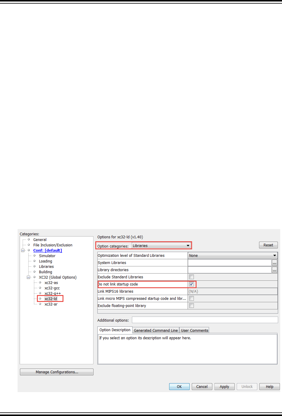
4.5.16 How Do I Use Library Files in My Project?
See 4.2.6 How Do I Build Libraries? for information on how you build your own library files. The compiler will
automatically include any applicable standard library into the build process when you compile, so you never need to
control these files.
To use one or more library files that were built by yourself or a colleague, include them in the list of files being
compiled on the command line. The library files can be specified in any position in the file list relative to the source
files, but if there is more than one library file, they will be searched in the order specified in the command line.
For example:
xc32-gcc -mprocessor=32MZ2048ECH100 main.c int.c mylib.a
If you are using MPLAB IDE to build a project, add the library file(s) to the Libraries folder that will shown in your
project, in the order in which they should be searched. The IDE will ensure that they are passed to the compiler at the
appropriate point in the build sequence.
4.5.17 How Do I Customize the C Runtime Startup Code?
Some applications may require an application-specific version of the C runtime startup code. For instance, you may
want to modify the startup code for an application loaded by a bootloader.
To customize the startup code for your application:
1. Start with the default startup code, a copy of which is located in the pic32m-libs.zip file located at:
<install-directory>/pic32-libs/
Once the file is unzipped, the source code can be found at:
pic32m-libs/libpic32/startup/crt0.S
2. Make a copy of this crt0.S file, rename it, and add it to your project.
3. Change your MPLAB X project to exclude the default startup code by enabling the “Do not link startup code”
under XC32 xc32-ld Option categories: Libraries page as shown below. When you build your project, the
MPLAB X IDE will build your new application-specific copy of the startup code rather than linking in the default
code.
Figure 4-1. Startup Code Properties Setting
XC32 Compiler for PIC32M
How To's
© 2020 Microchip Technology Inc.
User Guide
DS50002799B-page 49
4. You can now edit the assembly code in your new copy of the crt0.S file. The default source code uses macros
defined in the device-specific header files, which are included by xc.h. These macros define various device
specific behavior. Be sure to take this device-specific code into account when customizing your copy of the
code.
Table 4-1. Device-Specific Macros
Device-Specific Macro Description
__PIC32_SRS_SET_COUNT Defined to the number of Register Sets implemented on the
device. The default startup code uses this value to determine
how many register sets to use for $GP-register initialization.
__PIC32_HAS_L1CACHE Defined if the device features an L1 cache.
__PIC32_HAS_MIPS32R2 Defined if the device supports the MIPS32r2 Instruction Set.
__PIC32_HAS_MICROMIPS Defined if the device supports the microMIPS compressed
Instruction Set.
__PIC32_HAS_DSPR2 Defined if the device supports the DSPr2 Application-Specific
Extension.
__PIC32_HAS_FPU64 Defined if the device supports the single- and double-precision
hardware Floating Point Unit.
__PIC32_HAS_SSX Defined if the device does not require initialization of the bus
matrix registers in order to support execution from data
memory.
__PIC32_HAS_MMU_MZ_FIXED Defined if the device features a Memory Management Unit that
should be pre-initialized to a standard SQI and EBI mapping.
__PIC32_HAS_INIT_DATA Defined if the device requires data initialization by copying from
a template located in Flash to RAM.
4.5.18 What Optimizations Are Employed by the Compiler?
Code optimizations available depend on the edition of your compiler (see 19. Optimizations). A description of
optimization options can be found under 6.7.7 Options for Controlling Optimization.
4.5.19 Why Do I Get Out-of-Memory Errors When I Select a Debugger?
If you use a hardware tool debugger such as MPLAB PICkit 4 in-circuit debugger or MPLAB ICD 4 in-circuit debugger
memory is required for the on-board debug executive.
4.5.20 How Do I Stop My Project's Checksum From Changing?
The checksum that represents your built project (whether this is generated by the MPLAB X IDE or by tools such as
Hexmate) is calculated from the generated output of the compiler. Indeed, the algorithms used to obtain the
checksum are specifically designed so that even small changes in this output are almost guaranteed to produce a
different checksum result. Checksums are not calculated from your project’s source code. To ensure that your
checksum does not change from build to build, you must ensure that the output of the compiler does not change.
The following actions and situations could cause changes in the compiled output and hence changes in your project’s
checksum.
• Changing the source code, header files, or library code used by the project between builds.
• Changing the order in which source files or libraries are compiled or linked between builds.
• Having source code that makes using of macros such as __DATE__ and __TIME__, which produce output that
is dependent on when the project was built.
• Moving the location of source files between builds, where those files use macros such as __FILE__, which
produces output that is dependent on where the source file is located.
• Changing the compiler options between builds.
• Changing the compiler version between builds.
XC32 Compiler for PIC32M
How To's
© 2020 Microchip Technology Inc.
User Guide
DS50002799B-page 50

Note that the checksum algorithms used by tools such as Hexmate and the MPLAB X IDE can change, which can
result in a different checksum for the same compiler output. Such changes are rare, but check the compiler and IDE
release notes to see if the tools have been modified.
4.6 Fixing Code That Does Not Work
This section examines issues relating to projects that do not build due to compiler errors, or those that build, but do
not work as expected.
• 4.6.1 How Do I Set Up Warning/Error Messages?
• 4.6.2 How Do I Find the Code that Caused Compiler Errors or Warnings in My Program?
• 4.6.3 How Can I Stop Spurious Warnings From Being Produced?
• 4.6.4 Why Can’t I Even Blink an LED?
• 4.6.5 What Can Cause Corrupted Variables and Code Failure When Using Interrupts?
• 4.2 Invoking the Compiler
• 4.6.5 What Can Cause Corrupted Variables and Code Failure When Using Interrupts?
• 4.5.14 Why Are Some Objects Positioned Into Memory That I Reserved?
4.6.1 How Do I Set Up Warning/Error Messages?
To control message output, see 6.7.5 Options for Controlling Warning and Errors.
4.6.2 How Do I Find the Code that Caused Compiler Errors or Warnings in My Program?
In most instances, where the error is a syntax error relating to the source code, the message produced by the
compiler indicates the offending line of code (see 6.6 Compiler Messages). If you are compiling in MPLAB X IDE,
then you can double-click the message and have the editor take you to the offending line. But identifying the
offending code is not always so easy.
In some instances, the error is reported on the line of code following the line that needs attention. This is because a C
statement is allowed to extend over multiple lines of the source file. It is possible that the compiler cannot be able to
determine that there is an error until it has started to scan to statement following. So in the following code
input = PORTB // oops - forgot the semicolon
if(input>6)
// ...
The missing semicolon on the assignment statement will be flagged on the following line that contains the if()
statement.
In other cases, the error might come from the assembler, not the code generator. If the assembly code was derived
from a C source file, then the compiler will try to indicate the line in the C source file that corresponds to the assembly
that is at fault. If the source being compiled is an assembly module, the error directly indicates the line of assembly
that triggered the error. In either case, remember that the information in the error relates to some problem is the
assembly code, not the C code.
Finally, there are errors that do not relate to any particular line of code at all. An error in a compiler option or a linker
error are examples of these. If the program defines too many variables, there is no one particular line of code that is
at fault; the program as a whole uses too much data. Note that the name and line number of the last processed file
and source can be printed in some situations even though that code is not the direct source of the error.
At the top of each message description, on the right in brackets, is the name of the application that produced this
message. Knowing the application that produced the error makes it easier to track down the problem. The compiler
application names are indicated in 5. XC32 Toolchain and MPLAB X IDE.
If you need to see the assembly code generated by the compiler, look in the assembly list file. For information on
where the linker attempted to position objects, see the map file. See the MPLAB
®
XC32 Assembler, Linker and
Utilities User’s Guide (DS50002186) for information about the list and map files.
4.6.3 How Can I Stop Spurious Warnings From Being Produced?
Warnings indicate situations that could possibly lead to code failure. Always check your code to confirm that it is not a
possible source of error. In many situations the code is valid and the warning is superfluous. In this case, you may:
XC32 Compiler for PIC32M
How To's
© 2020 Microchip Technology Inc.
User Guide
DS50002799B-page 51

• Inhibit specific warnings by using the -Wno- version of the option.
• Inhibit all warnings with the -w option.
• In MPLAB X IDE, inhibit warnings in the Project Properties window under each tool category. Also look in the
Tool Options window, Embedded button, Suppressible Messages tab.
See 6.7.5 Options for Controlling Warning and Errors for details.
4.6.4 Why Can’t I Even Blink an LED?
Even if you have set up the TRIS register and written a value to the port, there are several things that can prevent
such a seemingly simple program from working.
• Make sure that the device’s configuration registers are set up correctly, as discussed in 8.4 Configuration Bit
Access. Make sure that you explicitly specify every bit in these registers and don’t just leave them in their default
state. All the configuration features are described in your device data sheet. If the configuration bits that specify
the oscillator source are wrong, for example, the device clock may not even be running.
• If the internal oscillator is being used, in addition to Configuration bits there may be SFRs you need to initialize
to set the oscillator frequency and modes, see 8.5 ID Locations and your device data sheet.
• To ensure that the device is not resetting because of the watchdog time, either turn off the timer in the
configuration bits or clear the timer in your code. There are library functions you can use to handle the watchdog
timer, described in the 32-bit Language Tool Libraries manual (DS51685). If the device is resetting, it may never
reach the lines of code in your program that blink the LED. Turn off any other features that may cause device
Reset until your test program is working.
• The device pins used by the port bits are often multiplexed with other peripherals. A pin might be connected to a
bit in a port, or it might be an analog input, or it might be the output of a comparator, for example. If the pin
connected to your LED is not internally connected to the port you are using, then your LED will never operate as
expected. The port function tables in your device data sheets will show other uses for each pin which will help
you identify peripherals to investigate.
4.6.5 What Can Cause Corrupted Variables and Code Failure When Using Interrupts?
This is usually caused by having variables used by both interrupt and main-line code. If the compiler optimizes
access to a variable or access is interrupted by an interrupt routine, then corruption can occur. See 4.4.4 How Do I
Share Data Between Interrupt and Main-line Code? for more information.
XC32 Compiler for PIC32M
How To's
© 2020 Microchip Technology Inc.
User Guide
DS50002799B-page 52

5. XC32 Toolchain and MPLAB X IDE
The 32-bit language tools may be used together under MPLAB X IDE to provide GUI development of application
code for the PIC32 MCU families of devices. The tools are:
• MPLAB XC32 C/C++ Compiler
• MPLAB XC32 Assembler
• MPLAB XC32 Object Linker
• MPLAB XC32 Object Archiver/Librarian and other 32-bit utilities
5.1 MPLAB X IDE and Tools Installation
In order to use the 32-bit language tools with MPLAB X IDE, you must install:
• MPLAB X IDE, which is available for free on the Microchip website.
• MPLAB XC32 C/C++ Compiler, which includes all of the 32-bit language tools. The compiler is available for free
(Free and Evaluation editions) or for purchase (Pro edition) on the Microchip website.
The 32-bit language tools will be installed, by default, in the directory:
• Windows OS - C:\Program Files\Microchip\xc32\x.xx
• Mac OS - /Applications/microchip/xc32/x.xx
• Linux OS - /opt/microchip/xc32/x.xx
where x.xx is the version number.
The executables for each tool will be in the bin subdirectory:
• C Compiler - xc32-gcc.exe
• Assembler - xc32-as.exe
• Object Linker - xc32-ld.exe
• Object Archiver/Librarian - xc32-ar.exe
• Other Utilities - xc32-utility.exe
All device include (header) files are located in the /pic32mx/include/proc subdirectory. These files are
automatically incorporated when you #include the xc.h header file.
Code examples are located in the examples directory.
5.2 MPLAB X IDE Setup
Once MPLAB X IDE is installed on your PC, launch the application and check the settings below to ensure that the
32-bit language tools are properly recognized.
1. From the MPLAB X IDE menu bar, select
Tools>Options to open the Options dialog. Click on the “Embedded”
button and select the “Build Tools” tab.
2. Click on “XC32” under “Toolchain.” Ensure that the paths are correct for your installation.
3. Click the OK button.
XC32 Compiler for PIC32M
XC32 Toolchain and MPLAB X IDE
© 2020 Microchip Technology Inc.
User Guide
DS50002799B-page 53

Figure 5-1. XC32 Tool Suite Locations in Windows
®
OS
5.3 MPLAB X IDE Projects
A project in MPLAB X IDE is a group of files needed to build an application, along with their associations to various
build tools. Below is a generic MPLAB X IDE project.
XC32 Compiler for PIC32M
XC32 Toolchain and MPLAB X IDE
© 2020 Microchip Technology Inc.
User Guide
DS50002799B-page 54
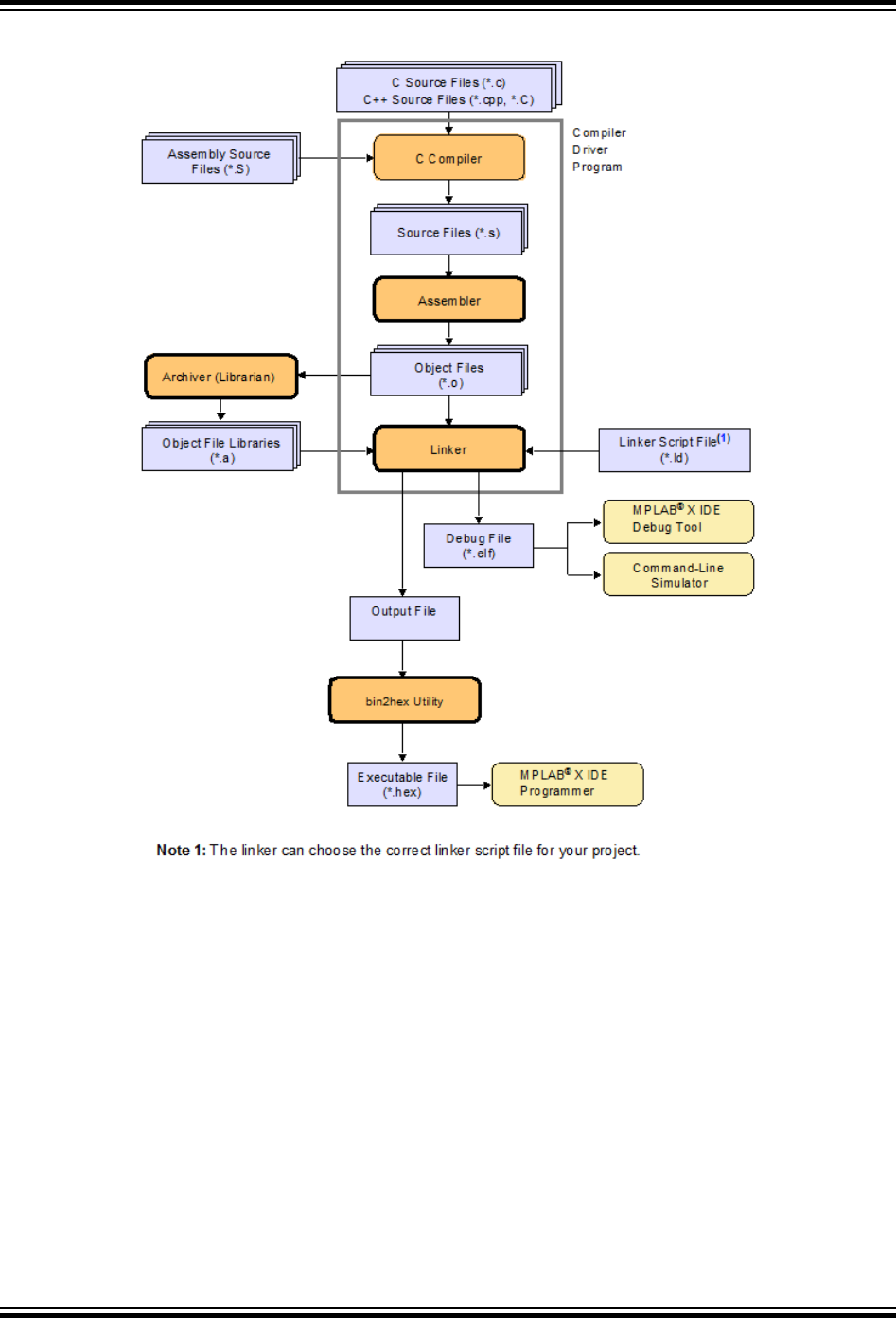
Figure 5-2. Compiler Project Relationships
In this MPLAB X IDE project, C source files are shown as input to the compiler. The compiler will generate source
files for input into the assembler. For more information on the compiler, see the compiler documentation.
Assembly source files are shown as input to the C preprocessor. The resulting source files are input to the assembler.
The assembler will generate object files for input into the linker or archiver. For more information on the assembler,
see the assembler documentation.
Object files can be archived into a library using the archiver/librarian. For more information on the archiver, see the
archiver/librarian documentation.
The object files and any library files, as well as a linker script file (generic linker scripts are added automatically), are
used to generate the project output files via the linker. The output file that may be generated by the linker is a debug
file (.elf) used by the simulator and debug tools which may be input into the bin2hex utility to produce an
executable file (.hex). For more information on linker script files and using the object linker, see the linker
documentation.
For more on projects and related workspaces, see MPLAB X IDE documentation.
XC32 Compiler for PIC32M
XC32 Toolchain and MPLAB X IDE
© 2020 Microchip Technology Inc.
User Guide
DS50002799B-page 55

5.4 Project Setup
To set up an MPLAB X IDE project for the first time, use the built-in Project Wizard (File>New Project). In this
wizard, you will be able to select a language toolsuite that uses the 32-bit language tools. For more on the wizard,
and MPLAB X IDE projects, see MPLAB X IDE documentation.
Once you have a project set up, you may then set up properties of the tools in MPLAB X IDE.
1. From the MPLAB X IDE menu bar, select
File>Project Properties to open a window to set/check project build
options.
2. Under “Conf:[default]”, select a tool from the tool collection to set up.
– 5.4.1 XC32 (Global Options)
– 5.4.2 xc32-as (32-bit Assembler)
– 5.4.3 xc32-gcc (32-bit C Compiler)
– 5.4.4 xc32-g++ (32-bit C++ Compiler)
– 5.4.5 xc32-ld (32-Bit Linker)
5.4.1 XC32 (Global Options)
Set up global options for all 32-bit language tools. See also 5.4.6 Options Page Features.
Table 5-1. XC32 (Global Options) All Options Category
Option Description Command Line
Use legacy lib Check this box to link with the
recommended Legacy Standard C
Library. Uncheck it to link with the
non-legacy Standard C Library
(HTC).
-legacy-libc and -no-legacy-
libc
Don’t delete intermediate files Don’t delete intermediate Files. Place
them in the object directory and
name them based on the source file.
-save-temps=obj
Use Whole-Program and Link-Time
Optimizations
When this feature is enabled, the
build will be constrained in the
following ways:
- The per-file build settings will be
ignored
- The build will no longer be an
incremental one (full build only)
-fwhole-program-flto
Use GP relative addressing threshold Put definitions of externally-visible
data in a small data section if that
data is no bigger than num bytes.
-G num
Common include dirs Directory paths entered here will be
appended to the already existing
include paths of the compiler.
Relative paths are from the MPLAB
X IDE project directory.
-I"dir"
5.4.2 xc32-as (32-bit Assembler)
A subset of command-line options may be specified in MPLAB X IDE. Select a category, and then set up assembler
options. For additional options, see MPLAB XC32 Assembler documentation. See also 5.4.6 Options Page Features.
XC32 Compiler for PIC32M
XC32 Toolchain and MPLAB X IDE
© 2020 Microchip Technology Inc.
User Guide
DS50002799B-page 56

Table 5-2. XC32-AS General Options Category
Option Description Command Line
Have symbols in production
build
Generate debugging information for source-level
debugging in MPLAB X.
--gdwarf-2
Keep local symbols Check to keep local symbols, that is, labels
beginning with .L (upper case only).
Uncheck to discard local symbols.
--keep-locals
Exclude floating-point library Exclude support for floating-point operations
reducing code size for applications that do not
require floating-point support.
-mno-float
Preprocessor macro definitions Project-specific preprocessor macro defines
passed via the compiler's –D option.
Assembler symbols Define symbol 'sym' to a given 'value'.
--defsym sym=value
Preprocessor Include directories Relative paths are from MPLAB X project
directory.
Assembler Include directories Relative paths are from MPLAB X project
directory.
Add a directory to the list of directories the
assembler searches for files specified
in .include directives.
You may add as many directories as necessary
to include a variety of paths. The current
working directory is always searched first and
then -I directories in the order in which they
were specified (left to right) here.
-I
Table 5-3. XC32-AS Other Options Category
Option Description Command Line
Diagnostics level Select warnings to display in the Output window.
- Generate warnings
- Suppress warnings
- Fatal warnings
--warn
--no-warn
--fatal-warnings
Include source code Check for a high-level language listing. High-
level listings require that the assembly source
code is generated by a compiler, a debugging
option like -g is given to the compiler, and
assembly listings (-al) are requested.
Uncheck for a regular listing.
-ah
Expand macros Check to expand macros in a listing.
Uncheck to collapse macros.
-am
Include false conditionals Check to include false conditionals
(.if, .ifdef) in a listing.
Uncheck to omit false conditionals.
-ac
XC32 Compiler for PIC32M
XC32 Toolchain and MPLAB X IDE
© 2020 Microchip Technology Inc.
User Guide
DS50002799B-page 57

...........continued
Option Description Command Line
Omit forms processing Check to turn off all forms processing that would
be performed by the listing
directives .psize, .eject, .title
and .sbttl.
Uncheck to process by listing directives.
-an
Include assembly Check for an assembly listing. This -a
suboption may be used with other suboptions.
Uncheck to exclude an assembly listing.
-al
List symbols Check for a symbol table listing.
Uncheck to exclude the symbol table from the
listing.
-as
Omit debugging directives Check to omit debugging directives from a
listing. This can make the listing cleaner.
Uncheck to included debugging directives.
-ad
List to file Use this option if you want the listing for a file.
The list file will have the same name as the asm
file plus .lst.
-a=$
{CURRENT_QUOTED_IF_SPA
CED_OBJECT_FILE_MINUS_
EXTENSION}.lst
5.4.3 xc32-gcc (32-bit C Compiler)
Although the MPLAB XC32 C/C++ Compiler works with MPLAB X IDE, it must be acquired separately. The full
version may be purchased, or a student (limited-feature) version may be downloaded for free. See the Microchip
website (www.microchip.com) for details.
A subset of command-line options may be specified in MPLAB X IDE. Select a category, and then set up compiler
options. For additional options, see the MPLAB X IDE User’s Guide (DS52027/DS50002027), also available on the
Microchip website.
See also 5.4.6 Options Page Features.
Table 5-4. XC32-GCC General Category
Option Description Command Line
Have symbols in production build Build for debugging in a production
build image.
-g
Enable App IO Support the APPIN/APPOUT
debugging feature with REAL ICE
-mappio-debug
XC32 Compiler for PIC32M
XC32 Toolchain and MPLAB X IDE
© 2020 Microchip Technology Inc.
User Guide
DS50002799B-page 58

...........continued
Option Description Command Line
Isolate each function in a section This option is often used with the
linker's --gc-sections option to
remove unreferenced functions.
Check to place each function into its
own section in the output file. The
name of the function determines the
section’s name in the output file.
Note: When you specify this option,
the assembler and linker may create
larger object and executable files and
will also be slower.
Uncheck to place multiple functions
in a section.
-ffunction-sections
Place data into its own section This option is often used with the
linker's --gc-sections option to
remove unreferenced statically-
allocated variables.
Place each data item into its own
section in the output file.
The name of the data item
determines the name of the section.
When you specify this option, the
assembler and linker may create
larger object and executable files and
will also be slower.
-fdata-sections
Use indirect calls Enable full-range calls.
-mlong-calls
Generate 16-bit code By default, generate code for the
MIPS16 instruction set, reducing
code size.
-mips16
Exclude floating-point library Exclude support for floating-point
operations reducing code size for
applications that do not require
floating-point support.
-mno-float
XC32 Compiler for PIC32M
XC32 Toolchain and MPLAB X IDE
© 2020 Microchip Technology Inc.
User Guide
DS50002799B-page 59

Table 5-5. XC32-GCC Optimization Category
Option Description Command Line
Optimization Level Select an optimization level. Your
compiler edition may support only
some optimizations. Equivalent to -
On option, where n is an option
below:
0 - Do not optimize.The compiler’s
goal is to reduce the cost of
compilation and to make debugging
produce the expected results.
1 - Optimize. Optimizing compilation
takes somewhat longer, and a lot
more host memory for a large
function. The compiler tries to reduce
code size and execution time.
2 - Optimize even more. The
compiler performs nearly all
supported optimizations that do not
involve a space-speed trade-off.
3 - Optimize yet more favoring speed
(superset of O2).
s - Optimize yet more favoring size
(superset of O2).
-On
Unroll loops This option often increases execution
speed at the expense of larger code
size.
Check to perform the optimization of
loop unrolling. This is only done for
loops whose number of iterations can
be determined at compile time or run
time.
Uncheck to not unroll loops.
-funroll-loops
Omit frame pointer Check to not keep the Frame Pointer
in a register for functions that don’t
need one.
Uncheck to keep the Frame Pointer.
-fomit-frame-pointer
Pre-optimization instruction
scheduling
Default for optimization level:
- Disable
- Enable
-fno-schedule-insns
-fschedule-insns
Post-optimization instruction
scheduling
Default for optimization level:
- Disable
- Enable
-fno-schedule-insns2
-fschedule-insns2
XC32 Compiler for PIC32M
XC32 Toolchain and MPLAB X IDE
© 2020 Microchip Technology Inc.
User Guide
DS50002799B-page 60
Table 5-6. XC32-GCC Preprocessing and Messages Category
Option Description Command Line
Preprocessor macros Project-specific preprocessor macro
defines passed via the compiler's –D
option.
Include directories Search these directories for project-
specific include files.
Make warnings into errors Check to halt compilation based on
warnings as well as errors.
Uncheck to halt compilation based
on errors only.
-Werror
Additional warnings Check to enable all warnings.
Uncheck to disable warnings.
-Wall
support-ansi Check to issue all warnings
demanded by strict ANSI C.
Uncheck to issue all warnings.
-ansi
strict-ansi Issue all the warnings demanded by
strict ISO C and ISO C++; reject all
programs that use forbidden
extensions, and some other
programs that do not follow ISO C
and ISO C++.
-pedantic
Use CCI syntax Enable support for the CCI syntax
(see 3. Common C Interface).
-mcci
Use IAR syntax Enable support for syntax used by
other toolchain vendors.
-mext=IAR
5.4.4 xc32-g++ (32-bit C++ Compiler)
A subset of command-line options may be specified in MPLAB X IDE. Select a category, and then set up linker
options. For additional options, see MPLAB Object Linker for 32-bit Devices documentation. See also 5.4.6 Options
Page Features.
Table 5-7. XC32-G++ C++ Specific Category
Option Description Command Line
Generate run time type
descriptor information
Enable generation of information about every
class with virtual functions for use by the C++
runtime type identification features
('dynamic_cast' and 'typeid'). If you don't use
those parts of the language, you can save some
space by disabling this option. Note that
exception handling uses the same information,
but it will generate it as needed. The
'dynamic_cast' operator can still be used for
casts that do not require runtime type
information, that is, casts to void * or to
unambiguous base classes.
-frtti
Enable C++ exception
handling
Enable exception handling. Generates extra
code needed to propagate exceptions.
-fexceptions
XC32 Compiler for PIC32M
XC32 Toolchain and MPLAB X IDE
© 2020 Microchip Technology Inc.
User Guide
DS50002799B-page 61

...........continued
Option Description Command Line
Check that the pointer
returned by operator 'new' is
non-null
Check that the pointer returned by operator new
is non-null before attempting to modify the
storage allocated.
-fcheck-new
Generate code to check for
violation of exception
specification
Generate code to check for violation of exception
specifications at runtime. Using this option may
increase code size in production builds.
-fenforce-eh-specs
Table 5-8. XC32-G++ General Category
Option Description Command Line
Have symbols in production
build
Build for debugging in a production build image.
-g
Enable App IO Place each function into its own section in the
output file if the target supports arbitrary
sections. The name of the function or the name
of the data item determines the section's name in
the output file. This option is useful when
combined with the linker’s --gc-sections
option to remove unreferenced functions.
-ffunction-sections
Place data into its own
section
Place each data item into its own section in the
output file if the target supports arbitrary
sections. The name of the function or the name
of the data item determines the section's name in
the output file. This option is useful when
combined with the linker’s --gc-sections
option to remove unreferenced variables.
-fdata-sections
Use indirect calls Enable full-range calls.
-mlong-calls
Generate 16-bit code By default, generate code for the MIPS16
instruction set, reducing code size.
-mips16
Exclude floating-point library Exclude support for floating-point operations
reducing code size for applications that do not
require floating-point support.
-mno-float
XC32 Compiler for PIC32M
XC32 Toolchain and MPLAB X IDE
© 2020 Microchip Technology Inc.
User Guide
DS50002799B-page 62

Table 5-9. XC32-G++ Optimization Category
Option Description Command Line
Optimization Level Select an optimization level. Your compiler
edition may support only some optimizations.
Equivalent to -On option, where n is an option
below:
0 - Do not optimize. The compiler’s goal is to
reduce the cost of compilation and to make
debugging produce the expected results.
1 - Optimize. Optimizing compilation takes
somewhat longer, and a lot more host memory
for a large function. The compiler tries to reduce
code size and execution time.
2 - Optimize even more. The compiler performs
nearly all supported optimizations that do not
involve a space-speed trade-off.
3 - Optimize yet more favoring speed (superset
of O2).
s - Optimize yet more favoring size (superset of
O2).
-On
Unroll loops Check to perform the optimization of loop
unrolling. This is only done for loops whose
number of iterations can be determined at
compile time or run time.
Uncheck to not unroll loops.
-funroll-loops
Omit frame pointer Check to not keep the Frame Pointer in a register
for functions that don’t need one.
Uncheck to keep the Frame Pointer.
-fomit-frame-pointer
Pre-optimization instruction
scheduling
Default for optimization level:
- Disable
- Enable
-fno-schedule-insns
-fschedule-insns
Post-optimization instruction
scheduling
Default for optimization level:
- Disable
- Enable
-fno-schedule-insns2
-fschedule-insns2
Table 5-10. XC32-G++ Preprocessing and Messages Category
Option Description Command Line
Preprocessor macros Project-specific preprocessor macro defines passed via the compiler’s
–D option.
Include directories Search these directories for project-specific include files.
Make warnings into
errors
Check to halt compilation based on warnings as well as errors.
Uncheck to halt compilation based on errors only.
-Werror
Additional warnings Check to enable all warnings.
Uncheck to disable warnings.
-Wall
XC32 Compiler for PIC32M
XC32 Toolchain and MPLAB X IDE
© 2020 Microchip Technology Inc.
User Guide
DS50002799B-page 63

...........continued
Option Description Command Line
support-ansi Check to issue all warnings demanded by strict ANSI C.
Uncheck to issue all warnings.
-ansi
strict-ansi Issue all the warnings demanded by strict ISO C and ISO C++; reject
all programs that use forbidden extensions, and some other programs
that do not follow ISO C and ISO C++.
-pedantic
Use CCI syntax Enable support for the CCI syntax (3. Common C Interface).
-mcci
Use IAR syntax Enable support for syntax used by other toolchain vendors.
-mext=IAR
5.4.5 xc32-ld (32-Bit Linker)
A subset of command-line options may be specified in MPLAB X IDE. Select a category, and then set up linker
options. For additional options, see MPLAB Object Linker for 32-bit Devices documentation. See also 5.4.6 Options
Page Features.
Table 5-11. XC32-LD General Category
Option Description Command Line
Heap Size (bytes) Specify the size of the heap in bytes. Allocate a
run-time heap of size bytes for use by C
programs. The heap is allocated from unused
data memory. If not enough memory is available,
an error is reported.
--
defsym=_min_heap_size=<si
ze>
Minimum stack size (bytes) Specify the minimum size of the stack in bytes.
By default, the linker allocates all unused data
memory for the run-time stack. Alternatively, the
programmer may allocate the stack by declaring
two global symbols: __SP_init and
__SPLIM_init. Use this option to ensure that
at least a minimum sized stack is available. The
actual stack size is reported in the link map
output file. If the minimum size is not available,
an error is reported.
--
defsym=_min_stack_size=<s
ize>
Allow overlapped sections Check to not check section addresses for
overlaps.
Uncheck to check for overlaps.
--check-sections
--no-check-sections
Remove unused sections Check to not enable garbage collection of
unused input sections (on some targets).
Uncheck to enable garbage collection.
--no-gc-sections
--gc-sections
Use response file to link Pass linker options in a file rather than on the
command line. On Windows systems, this option
allows you to properly link projects with a large
number of object files that would normally
overrun the command-line length limitation of the
Windows OS.
True
Additional driver options Type here any additional driver options not
existing in this GUI otherwise. The string you
introduce here will be emitted as is in the driver
invocation command.
XC32 Compiler for PIC32M
XC32 Toolchain and MPLAB X IDE
© 2020 Microchip Technology Inc.
User Guide
DS50002799B-page 64

Table 5-12. XC32-LD Fill Flash Memory Category
Option Description Command Line
Which areas to fill Specify which area of Flash memory to fill.
No Fill - None (default).
Fill All Unused - Fill all unused memory.
Provide Range to fill - Fill a range of memory.
Enter a range under “Memory Address Range”.
How to fill it Specify how to fill Flash memory.
Provide sequence of values - provide a
sequence under the Sequence option.
Constant or incrementing value - provide a
constant, increment/decrement or increment/
decrement constant under the same-named
option.
Sequence When Provide sequence of values is selected,
enter a sequence. The form is n1, n2, .... where
n1 uses C syntax. Example: 0x10, 25, 0x3F, 16.
--fill=sequence
Constant When Constant or incrementing value is
selected, enter a constant. Specify the constant
using C syntax (for example, 0x for hex, 0 for
octal). Example: 0x10 is the same as 020 or 16.
--fill=constant
Increment/Decrement When Constant or incrementing value is
selected, you can select to increment or
decrement the initial value of “Constant” on each
consecutive address.
No Incrementing - do not change constant
value.
Increment Const - increment the constant value
by the amount specified under the option
“Increment/Decrement Constant”.
Decrement Const - decrement the constant
value by the amount specified under the option
“Increment/Decrement Constant.”
Increment/Decrement
Constant
When Increment Const or Decrement Const is
selected, enter a constant increment or
decrement value. Specify the constant using C
syntax (for example, 0x for hex, 0 for octal).
Example: 0x10 is the same as 020 or 16.
--fill=constant+=incr
--fill=constant-=decr
Memory Address Range When Provide Range to fill is selected, enter
the range here. Specify range as Start:End
where Start and End use C syntax. Example
0x100:0x1FF is the same as 256:511.
--fill=value@range
XC32 Compiler for PIC32M
XC32 Toolchain and MPLAB X IDE
© 2020 Microchip Technology Inc.
User Guide
DS50002799B-page 65

Table 5-13. XC32-LD Libraries Category
Option Description Command Line
Optimization level of
Standard Libraries
Select an optimization level. Your compiler
edition may support only some optimizations.
Equivalent to -On option, where n is an option
below:
0 - Do not optimize. The compiler’s goal is to
reduce the cost of compilation and to make
debugging produce the expected results.
1 - Optimize. Optimizing compilation takes
somewhat longer, and a lot more host memory
for a large function. The compiler tries to reduce
code size and execution time.
2 - Optimize even more. The compiler performs
nearly all supported optimizations that do not
involve a space-speed trade-off.
3 - Optimize yet more favoring speed (superset
of O2).
s - Optimize yet more favoring size (superset of
O2).
-On
System Libraries Add libraries to be linked with the project files.
You may add more than one.
--library=name
Library directories Add a library directory to the library search path.
You may add more than one.
--library-path="name"
Exclude Standard Libraries Check to not use the standard system startup
files or libraries when linking. Only use library
directories specified on the command line.
Uncheck to use the standard system startup files
and libraries.
-nostdlib
Do no link startup code Exclude the default startup code because the
project provides application-specific startup code.
-nostartfiles
Generate 16-bit code Link the libraries precompiled for the MIPS16
instruction set, reducing code size.
-mips16
Exclude floating-point library Exclude support for floating-point operations
reducing code size for applications that do not
require floating-point support.
-mno-float
Table 5-14. XC32-LD Diagnostics Category
Option Description Command Line
Generate map file Create a map file.
-Map="file"
Display memory usage Check to print memory usage report.
Uncheck to not print a report.
--report-mem
Generate cross-reference file Check to create a cross-reference
table.
Uncheck to not create this table.
--cref
XC32 Compiler for PIC32M
XC32 Toolchain and MPLAB X IDE
© 2020 Microchip Technology Inc.
User Guide
DS50002799B-page 66
...........continued
Option Description Command Line
Warn on section realignment Check to warn if start of section
changes due to alignment.
Uncheck to not warn.
--warn-section-align
Trace Symbols Add/remove trace symbols.
--trace-symbol=symbol
Table 5-15. XC32-LD Symbols and Macros Category
Option Description Command Line
Linker symbols Create a global symbol in the output file
containing the absolute address (expr). You
may use this option as many times as necessary
to define multiple symbols in the command line.
A limited form of arithmetic is supported for the
expr in this context: you may give a
hexadecimal constant or the name of an existing
symbol, or use + and - to add or subtract
hexadecimal constants or symbols.
--defsym=sym
Preprocessor macro
definitions
Add linker macros.
-Dmacro
Symbols Specify symbol information in the output.
- Keep all
- Strip debugging info
- Strip all symbol info
—
--strip-debug (-S)
--strip-all (-s)
5.4.6 Options Page Features
The Options section of the Properties page has the following features for all tools:
Table 5-16. Page Features Options
Reset Reset the page to default values.
Additional options Enter options in a command-line (non-GUI) format.
Option Description Click on an option name to see information on the option in this window.
Not all options have information in this window.
Generated Command Line Click on an option name to see the command-line equivalent of the
option in this window.
5.5 Project Example
In this example, you will create an MPLAB X IDE project with two C code files.
5.5.1 Run the Project Wizard
In MPLAB X IDE, select File>New Project to launch the wizard.
1. Choose Project: Select “Microchip Embedded” for the category and “Standalone Project” for the project. Click
Next> to continue.
2. Select Device: Select the dsPIC30F6014. Click Next> to continue.
3. Select Header: There is no header for this device so this is skipped.
XC32 Compiler for PIC32M
XC32 Toolchain and MPLAB X IDE
© 2020 Microchip Technology Inc.
User Guide
DS50002799B-page 67

4. Select Tool: Choose a development tool from the list. Tool support for the selected device is shown as a
colored circle next to the tool. Mouse over the circle to see the support as text. Click Next> to continue.
5. Select Compiler: Choose a version of the XC32 toolchain. Click Next> to continue.
6. Select Project Name and Folder: Enter a project name, such as MyXC32Project. Then select a location for
the project folder. Click Finish to complete the project creation and setup.
Once the Project Wizard has completed, the Project window should contain the project tree. For more on projects,
see the MPLAB X IDE documentation.
5.5.2 Set Build Options
Select File>Project Properties or right click on the project name and select “Properties” to open the Project Properties
dialog.
1. Under “Conf:[default]>XC32 (Global Options)”, select “xc32-gcc.”
2. Under “Conf:[default]>XC32 (Global Options)”, select “xc32-ld.”
3. Select “Diagnostics” from the “Option Categories.” Then enter a file name to “Generate map file,” that is,
example.map.
4. Click the OK button on the bottom of the dialog to accept the build options and close the dialog.
5.5.3 Build the Project
Right-click on the project name, “MyXC32Project,” in the project tree and select “Build” from the pop-up menu. The
Output window displays the build results.
If the build did not complete successfully, check these items:
1. Review the previous steps in this example. Make sure you have set up the language tools correctly and have
all the correct project files and build options.
2. If you modified the sample source code, examine the Build tab of the Output window for syntax errors in the
source code. If you find any, click on the error to go to the source code line that contains that error. Correct the
error, and then try to build again.
5.5.4 Output Files
View the project output files by opening the files in MPLAB X IDE.
1. Select File>Open File. In the Open dialog, find the project directory.
2. Under “Files of type” select “All Files” to see all project files.
3. Select File>Open File. In the Open dialog, select “example.map.” Click Open to view the linker map file in an
MPLAB X IDE editor window. For more on this file, see the linker documentation.
4. Select File>Open File. In the Open dialog, return to the project directory and then go to the
dist>default>production directory. Notice that there is only one hex file, “MyXC32Project.X.production.hex.”
This is the primary output file. Click Open to view the hex file in an MPLAB X IDE editor window. For more on
this file, see the Utilities documentation.
There is also another file, “MyXC32Project.X.production.elf.” This file contains debug information and is used
by debug tools to debug your code. For information on selecting the type of debug file, see 5.4.1 XC32
(Global Options).
5.5.5 Further Development
Usually, your application code will contain errors and not work the first time. Therefore, you will need a debug tool to
help you develop your code. Using the output files previously discussed, several debug tools exist that work with
MPLAB X IDE to help you do this. You may choose from simulators, in-circuit emulators or in-circuit debuggers, either
manufactured by Microchip Technology or third-party developers. Please see the documentation for these tools to
learn how they can help you. When debugging, you will use Debug>Debug Project to run and debug your code.
Please see MPLAB X IDE documentation for more information.
Once you have developed your code, you will want to program it into a device. Again, there are several programmers
that work with MPLAB X IDE to help you do this. Please see the documentation for these tools to see how they can
help you. When programming, you will use “Make and Program Device Project” button on the debug toolbar. Please
see MPLAB X IDE documentation concerning this control.
XC32 Compiler for PIC32M
XC32 Toolchain and MPLAB X IDE
© 2020 Microchip Technology Inc.
User Guide
DS50002799B-page 68

6. Command-line Driver
The MPLAB XC32 C Compiler command-line driver, xc32-gcc, can be invoked to perform all aspects of compilation,
including C code generation, assembly and link steps. Its use is the recommended way to invoke the compiler, as it
hides the complexity of all the internal applications and provides a consistent interface for all compilation steps. Even
if an IDE is used to assist with compilation, the IDE will ultimately call xc32-gcc.
If you are developing a project that contains C++ source code, an alternate driver called xc32-g++ is supplied and
that will link in an alternate set of libraries. Its operation is similar to the xc32-gcc driver.
This chapter describes the steps that the driver takes during compilation, the files that the driver can accept and
produce, as well as the command-line options that control the compiler’s operation.
6.1 Invoking The Compiler
This section explains how to invoke xc32-gcc on the command line and discusses the input files that can be passed
to the compiler.
Environment variables that can be set to specify certain aspects of the compiler's behavior are also explained.
6.1.1 Driver Command-line Format
The xc32-gcc driver can be used to compile and assemble C and assembly source files, as well as link object files
and library archives to form a final program image.
The xc32-g++ driver must instead be used when the module source is written in C++.
The driver has the following basic command format:
xc32-gcc [options] files
So, for example, to compile and link the C source file hello.c, you could use the command:
xc32-gcc -mprocessor=32MZ2048ECH100 -O2 -o hello.elf hello.c
The format for the C++ driver is similar.
xc32-g++ [options] files
And this driver is used in a similar way, for example:
xc32-g++ -mprocessor=32MZ2048ECH100 -O2 -o hello.elf hello.cpp
Throughout this manual, it is assumed that the compiler applications are in your console’s search path. See 6.1.2
Environment Variables for information on the environment variable that specifies the search locations. Alternatively,
use the full directory path along with the driver name when executing the compiler.
It is customary to declare options (identified by a leading dash “-” or double dash “--”) before the files’ names;
however, this is not mandatory.
Command-line options are case sensitive, with their format and description being supplied in 6.7 Driver Option
Descriptions. Many of the command-line options accepted by xc32-gcc are common to all the MPLAB XC
compilers, to allow greater portability between devices and compilers.
The files can be any mixture of C/C++ and assembler source files, as well as relocatable object files and archive
files. While the order in which these files are listed does not directly affect the operation of the program, it can affect
the allocation of code or data. Note, that the order of the archive files will dictate the order in which they are
searched, and in some situations, this might affect which modules are linked in to the program.
It is recommended that C-only projects use the xc32-gcc driver. If you have C++ source code or a mix of C and C++
source, always use xc32-g++ driver to ensure the correct libraries are linked in.
XC32 Compiler for PIC32M
Command-line Driver
© 2020 Microchip Technology Inc.
User Guide
DS50002799B-page 69

6.1.2 Environment Variables
The environment variables in this section are optional, but, if defined, they will be used by the compiler. The compiler
driver, or other subprogram, may choose to determine an appropriate value for some of the following environment
variables if they are not set. The driver, or other subprogram, takes advantage of internal knowledge about the
installation of the compiler. As long as the installation structure remains intact, with all subdirectories and executables
remaining in the same relative position, the driver or subprogram will be able to determine a usable value.
The XC32-style variables should be used for new projects; however, the PIC32-style variables may be used for
legacy projects.
Table 6-1. Compiler-Related Environment Variables
Variable Description
XC32_C_INCLUDE_PATH or
PIC32_C_INCLUDE_PATH
This variable’s value is a semicolon-separated list of directories, much like your
host terminal's PATH environment variable. When the compiler searches for header
files, it tries the directories listed in the variable, after the directories specified with
-I but before the standard header file directories.
If the environment variable is undefined, the preprocessor chooses an appropriate
value based on the standard installation. By default, the following directories are
searched for the following include files:
<install-path>\pic32mx\include
XC32_COMPILER_PATH or
PIC32_COMPILER_PATH
The value of this variable is a semicolon-separated list of directories, much like
your host terminal's PATH environment variable. The compiler tries the directories
thus specified when searching for subprograms, if it can’t find the subprograms
using PIC32_EXEC_PREFIX
XC32_EXEC_PREFIX or
PIC32_EXEC_PREFIX
If this environment variable is set, it specifies a prefix to use in the names of
subprograms executed by the compiler. No directory delimiter is added when this
prefix is combined with the name of a subprogram, but you can specify a prefix that
ends with a slash if you wish. If the compiler cannot find the subprogram using the
specified prefix, it tries looking in your PATH environment variable.
If the environment variable is not set or set to an empty value, the compiler driver
chooses an appropriate value based on the standard installation. If the installation
has not been modified, this will result in the driver being able to locate the required
subprograms.
Other prefixes specified with the -B command line option take precedence over the
user- or driver-defined value of the variable.
Under normal circumstances it is best to leave this value undefined and let the
driver locate subprograms itself.
XC32_LIBRARY_PATH or
PIC32_LIBRARY_PATH
This variable’s value is a semicolon-separated list of directories, much like PATH.
This variable specifies a list of directories to be passed to the linker. The driver’s
default evaluation of this variable is:
<install-path>\lib;
<install-path>\pic32mx\lib
TMPDIR
If this variable is set, it specifies the directory to use for temporary files. The
compiler uses temporary files to hold the output of one stage of compilation that is
to be used as input to the next stage: for example, the output of the preprocessor,
which is the input to the compiler proper.
6.1.3 Input File Types
The xc32-gcc driver distinguishes source files, intermediate files and library files solely by the file type, or extension.
The following case-sensitive extensions, listed below are recognized.
XC32 Compiler for PIC32M
Command-line Driver
© 2020 Microchip Technology Inc.
User Guide
DS50002799B-page 70
Table 6-2. Input File Types
Extension File format
.c
C source file
.i
Preprocessed C source file
.cpp
C++ source file
.ii
Preprocessed C++ source file
.s
Assembler source file
.S
Assembly source file requiring preprocessing
.o
Relocatable object code file
.a
Archive (library) file
other A file to be passed to the linker
There are no compiler restrictions imposed on the names of source files, but be aware of case, name-length, and
other restrictions that are imposed by your host operating system.
Avoid using the same base name for assembly and C/C++ source files, even if they are located in different
directories. So, for example, if a project contains a C source file called init.c, do not also add to the project an
assembly source file with the name init.s. Avoid, also, having source files with the same base name as the
MPLAB X IDE project name.
The terms source file and module are often used interchangeably, but they refer to the source code at different points
in the compilation sequence.
A source file is a file that contains all or part of a program. It may contain C/C++ code, as well as preprocessor
directives and commands. Source files are initially passed to the preprocessor by the compiler driver.
A module is the output of the preprocessor for a given source file, after the inclusion of any header files specified
by#include preprocessor directives, and after the processing and subsequent removal of other preprocessor
directives (with the possible exception of some commands for debugging). Thus, a module is usually the
amalgamation of a source file and several header files, and it is this output that is passed to the remainder of the
compiler applications. A module is also referred to as a translation unit.
Like assembly source files, these terms can also be applied to assembly files, which can be preprocessed and can
include other header files.
6.2 The C Compilation Sequence
When you compile a project, many internal applications are called by the driver to do the work. This section
introduces these internal applications and describes how they relate to the build process, especially when a project
consists of multiple source files. This information should be of particular interest if you are using a make system to
build projects.
6.2.1 Single-Step C Compilation
Full compilation of one or more C source files, including the link step, can be performed in just one command using
the xc32-gcc driver.
6.2.1.1 Compiling a Single C File
The following is a simple C program that adds two numbers. To illustrate how to compile and link a program
consisting of a single C source file, copy the code into any text editor and save it as a plain text file with the name
ex1.c.
#include <xc.h>
unsigned int
XC32 Compiler for PIC32M
Command-line Driver
© 2020 Microchip Technology Inc.
User Guide
DS50002799B-page 71

add(unsigned int a, unsigned int b)
{
return a + b;
}
int
main(void)
{
unsigned int x, y, z;
x = 2;
y = 5;
z = add(x, y);
return 0;
}
In the interests of clarity, this code does not specify device configuration bits, nor has any useful purpose.
Compile the program by typing the following command at the prompt in your favorite terminal. For the purpose of this
discussion, it is assumed that in your terminal you have changed into the directory containing the source file you just
created, and that the compiler is installed in the standard directory location and is in your host's search path.
xc32-gcc -mprocessor=32MZ2048ECH100 -o ex1.elf ex1.c
This command compiles the ex1.c source file for a 32MZ2048ECH100 device and has the output written to
ex1.elf, which may be loaded into the MPLAB X IDE.
If a hex file is required, for example, to load into a device programmer, then use the following command:
xc32-bin2hex ex1.elf
This creates an Intel hex file named ex1.hex.
The driver will compile the source file, regardless of whether it has changed since the last build command.
Development environments (such as MPLAB X IDE) and make utilities must be employed to achieve incremental
builds (see 6.2.2 Multi-Step C Compilation).
Unless otherwise specified, an ELF file (this is by default called a.out) is produced as the final output.
6.2.1.2 Compiling Multiple C Files
This section demonstrates how to compile and link a project, in a single step, that consists of multiple C source files.
Copy the example code shown into a text file called add.c.
/* add.c */
#include <xc.h>
unsigned int
add(unsigned int a, unsigned int b)
{
return a + b;
}
And place the following code in another file, ext.c.
/* ex1.c */
#include <xc.h>
unsigned int add(unsigned int a, unsigned int b);
int
main(void) {
unsigned int x, y, z;
x = 2;
y = 5;
z = add(x, y);
return 0;
}
XC32 Compiler for PIC32M
Command-line Driver
© 2020 Microchip Technology Inc.
User Guide
DS50002799B-page 72

In the interests of clarity, this code does not specify device configuration bits, nor has any useful purpose.
Compile both files by typing the following at the prompt:
xc32-gcc -mprocessor=32MZ2048ECH100 -o ex1.elf ex1.c add.c
This command compiles the modules ex1.c and add.c in the one step. The compiled modules are linked with the
relevant compiler libraries and the executable file ex1.elf is created.
6.2.2 Multi-Step C Compilation
A multi-step compilation method can be employed to build projects consisting of one or more C source files. Make
utilities can use this feature, taking note of which source files have changed since the last build to speed up
compilation. Incremental builds are also be performed by integrated development environments, such as the MPLAB
X IDE when selecting the Build Project icon or menu item.
Make utilities typically call the compiler multiple times: once for each source file to generate an intermediate file and
once to perform the second stage compilation, which links the intermediate files to form the final output. If only one
source file has changed since the last build, the intermediate file corresponding to the unchanged source file need
not be regenerated.
For example, the files ex1.c and add.c are to be compiled using a make utility. The command lines that the make
utility could use to compile these files might be something like:
xc32-gcc -mprocessor=32MZ2048ECH100 -c ex1.c
xc32-gcc -mprocessor=32MZ2048ECH100 -c add.c
xc32-gcc -mprocessor=32MZ2048ECH100 -o ex1.elf ex1.o add.o
The -c option used with the first two commands will compile the specified file into the intermediate file format, but not
link. The resultant intermediate files are linked in the final step to create the final output ex1.elf. All the files that
constitute the project must be present when performing the second stage of compilation.
The above example uses the command-line driver, xc32-gcc, to perform the final link step. You can explicitly call
the linker application, pic32m-ld, but this is not recommended as the commands are complex and when driving the
linker application directly, you must specify linker options, not driver options, as shown above.
For more information on using the linker, see the MPLAB
®
XC32 Assembler, Linker and Utilities User’s Guide
relevant to your project.
You may also wish to generate intermediate files to construct your own library archive files.
See MPLAB
®
XC32 Assembler, Linker and Utilities User’s Guide relevant to your project for more information on
library creation.
6.3 The C++ Compilation Sequences
When you compile a project, many internal applications are called by the driver to do the work. This section
introduces these internal applications and describes how they relate to the build process, especially when a project
consists of multiple source files. This information should be of particular interest if you are using a make system to
build projects.
6.3.1 Single-step C++ Compilation
A single command-line instruction can be used to compile one file or multiple files.
6.3.1.1 Compiling a Single C++ File
The following is a simple C++ program. To illustrate how to compile and link a program consisting of a single C++
source file, copy the code into any text editor and save it as a plain text file with the name ex2.cpp.
/* ex2.cpp */
#include <xc.h>
#include <iostream>
#include <vector>
XC32 Compiler for PIC32M
Command-line Driver
© 2020 Microchip Technology Inc.
User Guide
DS50002799B-page 73

#include <deque>
#include <list>
#include <set>
#include <map>
#include <string>
#include <algorithm>
#include <iterator>
#include <functional>
#include <numeric>
using namespace std;
//Device - Specific Configuration - bit settings
#pragma config FPLLMUL=MUL_20, FPLLIDIV=DIV_2, FPLLODIV=DIV_1
#pragma config FWDTEN=OFF
#pragma config POSCMOD=HS, FNOSC=PRIPLL, FPBDIV=DIV_8
template < class T >
inline void
print_elements(const T & coll, const char *optcstr = "") {
typename T::const_iterator pos;
std::cout << optcstr;
for (pos = coll.begin(); pos != coll.end(); ++pos) {
std::cout << *pos << ' ';
}
std::cout << std::endl;
}
template < class T >
inline void
insert_elements(T & coll, int first, int last) {
for (int i = first; i <= last; ++i) {
coll.insert(coll.end(), i);
}
}
int
main(void) {
//Direct stdout to UART 1 for use with the simulator
__XC_UART = 1;
deque<int>coll;
insert_elements(coll, 1, 9);
insert_elements(coll, 1, 9);
print_elements(coll, "on entry: ");
// sortelements
sort(coll.begin(), coll.end());
print_elements(coll, "sorted: ");
//sorted reverse
sort(coll.begin(), coll.end(), greater < int >());
print_elements(coll, "sorted >: ");
while (1);
}
The first line of the program includes the header file xc.h, which provides definitions for all Special Function
Registers (SFRs) on the target device. The second file of the program includes the header file, which provides the
necessary prototypes for the peripheral library.
Compile the program by typing the following command at the prompt in your favorite terminal. For the purpose of this
discussion, it is assumed that in your terminal you have changed into the directory containing the source file you just
created, and that the compiler is installed in the standard directory location and is in your host's search path.
xc32-g++ -mprocessor=32MX795F512L -Wl,--defsym=_min_heap_size=0xF000 -o ex2.elf ex2.cpp
The option -o ex2.elf names the output executable file. This elf file may be loaded into MPLAB X IDE.
If a hex file is required, for example, to load into a device programmer, then use the following command
xc32-bin2hex ex2.elf
This creates an Intel hex file named ex2.hex.
6.3.2 Compiling Multiple C and C++ Files
This section demonstrates how to compile and link multiple C and C++ files in a single step.
XC32 Compiler for PIC32M
Command-line Driver
© 2020 Microchip Technology Inc.
User Guide
DS50002799B-page 74

File 1
/* main.cpp */
#include <xc.h>
#include <iostream>
using namespace std;
//Device - Specific Configuration - bit settings
#pragma config FPLLMUL=MUL_20, FPLLIDIV=DIV_2, FPLLODIV=DIV_1
#pragma config FWDTEN=OFF
#pragma config POSCMOD=HS, FNOSC=PRIPLL, FPBDIV=DIV_8
// add() must have C linkage
extern "C" {
extern unsigned int add(unsigned int a, unsigned int b);
}
int main(void) {
int myvalue = 6;
//Direct stdout to UART 1 for use with the simulator
__XC_UART = 1;
std::cout << "original value: " << myvalue << endl;
myvalue = add(myvalue, 3);
std::cout << "new value:
while (1);
}
File 2
/* ex3.c */
unsigned int
add(unsigned int a, unsigned int b)
{
return(a+b);
}
Compile both files by typing the following at the prompt:
xc32-g++ -mprocessor=32MX795F512L -o ex3.elf main.cpp ex3.c
The command compiles the modules main.cpp and ex3.c. The compiled modules are linked with the compiler
libraries for C++ and the executable file ex3.elf is created.
Note: Use the xc32-g++ driver (as opposed to the xc32-gcc driver) in order to link the project with the C++ support
libraries necessary for the C++ source file in the project.
6.4 Runtime Files
In addition to the C/C++ and assembly source files and user-defined libraries specified on the command line, the
compiler can also link into your project compiler-generated source files and pre-compiled library files, whose content
falls into the following categories:
• C/C++ standard library routines
• Implicitly called arithmetic library routines
• User-defined library routines
• The runtime start-up code
Note: Some PIC32 target devices allow you to select to boot in either the MIPS32
®
or microMIPS
™
ISA mode via a
device configuration bit (BOOTISA). On these devices, if your BOOTISA bit is set to microMIPS mode, pass the -
mmicromips mode to the xc32-gcc/g++ compilation driver to tell it to link with the microMIPS variant of the runtime
start-up code. If your BOOTISA bit is set to MIPS32 mode, pass the -mno-micromips option to the compilation
driver so that the MIPS32 variant of the runtime start-up code is linked.
6.4.1 Location and Naming Convention
By default, the compiler uses the directory <install-directory>/lib/gcc/ to store the specific libraries and
the directory <install-directory>/pic32mx/lib to store the target-specific libraries, based on the target
device family.
XC32 Compiler for PIC32M
Command-line Driver
© 2020 Microchip Technology Inc.
User Guide
DS50002799B-page 75

The target libraries that are distributed with the compiler are built for the corresponding command-line options:
• Size vs. speed (-Os vs. -O3)
• MIPS16 vs. MIPS32 vs. microMIPS ISA mode (-mips16 vs. -mno-mips16 vs. -mmicromips)
• Software floating-point vs no floating-point support (-msoft-float vs. -mno-float)
The following examples provide details on which of the library subdirectories are searched.
If no optimization option has been specified or an optimization of level 2 or lower has been specified, for example,
xc32-gcc -O1 foo.c, then the libraries in the top-level of the library subdirectories are used.
If -Os level optimizations have been chosen, for example, xc32-g++ -Os foo.cpp, then the libraries in the size
directories of the library subdirectories are used.
If -Os level optimizations and the MIPS16 instruction set option have both been chosen, for example, xc32-gcc -
Os -mips16 foo.c, then the libraries in the size/mips16 directories of the library subdirectories are searched.
6.4.2 Library Files
The names of the C/C++ standard library files appropriate for the selected target device, and other driver options, are
determined by the driver.
The target libraries, called multilibs, are built multiple times with a permuted set of options. When the compiler driver
is called to compile and link an application, the driver chooses the version of the target library that has been built with
the same options.
By default, the 32-bit language tools use the directory <install-directory>/lib/gcc/ to store the specific
libraries and the directory <install-directory>/pic32mx/lib to store the target-specific libraries. Both of
these directory structures contain subdirectories for each of the multilib combinations specified above.
The target libraries that are distributed with the compiler are built for the corresponding command-line options:
• Size vs speed (-Os vs. -O3)
• MIPS16 vs MIPS32 vs microMIPS ISA mode (-mips16 vs. -mno-mips16 vs -mmicromips)
• Software floating-point vs no floating-point support (-msoft-float vs -mno-float)
The following examples provide details on which of the multilibs subdirectories are chosen.
xc32-gcc foo.c
xc32-g++ foo.cpp
For this example, no command line options have been specified (that is, the
default command line options are being used). In this case, the .subdirectories
are used.
xc32-gcc -Os foo.c
xc32-g++ -Os foo.cpp
For this example, the command line option for optimizing for size has been
specified (that is, -Os is being used). In this case, the ./size subdirectories are
used.
xc32-gcc -O2 foo.c
xc32-g++ -O2 foo.cpp
For this example, the command line option for optimizing has been specified;
however, this command line option optimizes for neither size nor space (that is, -
O2 is being used). In this case, the .subdirectories are used.
xc32-gcc -Os -mips16
foo.c
xc32-g++ -Os -mips16
foo.cpp
For this example, the command line options for optimizing for size and for
MIPS16 code have been specified (that is, -Os and -mips16 are being used). In
this case, the ./size/mips16 subdirectories are used.
6.4.2.1 Standard Libraries
The C/C++ standard libraries contain a standardized collection of functions, such as string, math and input/output
routines. The range of these functions are described in 17. Library Routines.
These libraries also contain C/C++ routines that are implicitly called by the output code of the code generator. These
are routines that perform tasks such as floating-point operations and that may not directly correspond to a C/C++
function call in the source code.
XC32 Compiler for PIC32M
Command-line Driver
© 2020 Microchip Technology Inc.
User Guide
DS50002799B-page 76

6.4.2.2 User-Defined Libraries
User-defined libraries may be created and linked in with programs as required. Library files are more easy to manage
and may result in faster compilation times, but must be compatible with the target device and options for a particular
project. Several versions of a library may need to be created to allow it to be used for different projects.
User-created libraries that should be searched when building a project can be listed on the command line along with
the source files.
As with Standard C/C++ library functions, any functions contained in user-defined libraries should have a declaration
added to a header file. It is common practice to create one or more header files that are packaged with the library file.
These header files can then be included into source code when required.
6.4.3 Peripheral Library Functions
For PIC32MX devices only:
Many of the peripherals of the PIC32 devices are supported by the peripheral library functions provided with the
compiler tools. Please refer to the MPLAB
®
Harmony Libraries for new projects. For legacy support, these PLIB
Libraries will be available for download from http://www.microchip.com/pic32_peripheral_lib.
For All PIC32M devices:
MPLAB Harmony includes a set of peripheral libraries, drivers and system services that are readily accessible for
application development. For access to the peripheral header files, go to the Microchip web site
(www.microchip.com), click on the Design Support tab and download MPLAB Harmony and MPLAB Code
Configurator. The path to the peripheral libraries is:
For Windows: C:\microchip\harmony\<version>\framework\peripheral
For Mac/Linux: ~\microchip\harmony\<version>\framework\peripheral
6.4.4 Runtime Startup Code Location
The runtime startup code is contained in multiple versions of precompiled object file modules, to support architectural
differences between device families.
For C programs, there is only one start-up module.
The source code for this module can be found in the pic32m-libs.zip file located at <install-directory>/
pic32-libs/. Once the file is unzipped, the source code can be found at: pic32m-libs/libpic32/startup/
crt0.S. It is precompiled into the following library location: <install-directory>/pic32mx/lib/crt0.o.
For C++ programs, code from five object files link sequentially to create a single initialization routine, which initializes
the C++ runtime environment.
The PIC32M precompiled startup object modules are located in the following location: <install-directory>/
pic32mx/lib/. The files have the names: cpprt0.o, crti.o, and crtn.o. The precompiled startup modules are
located in the following location: <install-directory>/lib/gcc/pic32mx/<gcc-version>/. The files have
the names: crtbegin.o and crtend.o.
6.4.5 Startup and Initialization
Note: Some PIC32 target devices allow you to select to boot in either the MIPS32
®
or microMIPS
™
ISA mode via a
device configuration bit (BOOTISA). On these devices, if your BOOTISA bit is set to microMIPS mode, pass the -
mmicromips mode to the xc32-gcc/g++ compilation driver to tell it to link with the microMIPS variant of the runtime
start-up code. If your BOOTISA bit is set to MIPS32 mode, pass the -mno-micromips option to the compilation
driver so that the MIPS32 variant of the runtime start-up code is linked.
The runtime startup code performs initialization tasks that must be executed before the main() function in the C/C++
program is executed. For information on the tasks performed by this code, see 16. Main, Runtime Start-up and
Reset.
The compiler will select the appropriate runtime startup code, based on the selected target device and other compiler
options.
• The startup code initializes the L1 cache when available.
XC32 Compiler for PIC32M
Command-line Driver
© 2020 Microchip Technology Inc.
User Guide
DS50002799B-page 77
• It enables the DSPr2 engine when available.
• It also initializes the Translation Lookaside Buffer (TLB) of the Memory Management Unit (MMU) for the External
Bus Interface (EBI) or Serial Quad Interface (SQI) when available. The device-specific linker script creates a
table of TLB initialization values that the startup code uses to initialize the TLB at startup.
Important: When your target MCU is configured to use the microMIPS compressed ISA at startup (and
for interrupts/exceptions), be sure to pass the -mmicromips option to xc32-gcc when linking, and use the
micromips function attribute on all of your Interrupt Service Routines (ISRs). Using the -mmicromips
option and the micromips attribute ensures that your startup code and ISR code are compiled for the
microMIPS ISA when the BOOTISA Configuration bit is set to micromips. Likewise, be sure that you
linkwith the MIPS32 startup code, and your ISRs are not micromips attributed when the BOOTISA bit is
set to MIPS32.
For C:
There is only one start-up module, which initializes the C runtime environment.
The source code for this is found in the pic32m-libs.zip file located at:
<install-directory>/pic32-libs/
Once the file is unzipped, the source code can be found at:
pic32m-libs/libpic32/startup/crt0.S.
It is precompiled into the following library location:
<install-directory>/pic32mx/lib/crt0.o.
Multilib versions of these modules exist in order to support architectural differences between device families.
For C++:
Code from five object files link sequentially to create a single initialization routine, which initializes the C++ runtime
environment.
The PIC32M precompiled startup objects are located in the following location:
<install-directory>/pic32mx/lib/.
The files have the following names: cpprt0.o, crti.o, and crtn.o.
The GCC precompiled startup objects are located in the following location:
<install-directory>/lib/gcc/pic32mx/<gcc-version>/.
The files have the following names: crtbegin.o and crtend.o.
Multilib variations of these modules exist in order to support architectural differences between device families and
also optimization settings.
For more information about what the code in these start-up modules actual does, see 16.2 Runtime Start-Up Code.
6.5 Compiler Output
There are many files created by the compiler during the compilation. A large number of these are intermediate files
and some are deleted after compilation is complete, but many remain and are used for programming the device, or
for debugging purposes.
6.5.1 Output Files
The compilation driver can produce output files with the following extensions, which are case-sensitive.
XC32 Compiler for PIC32M
Command-line Driver
© 2020 Microchip Technology Inc.
User Guide
DS50002799B-page 78
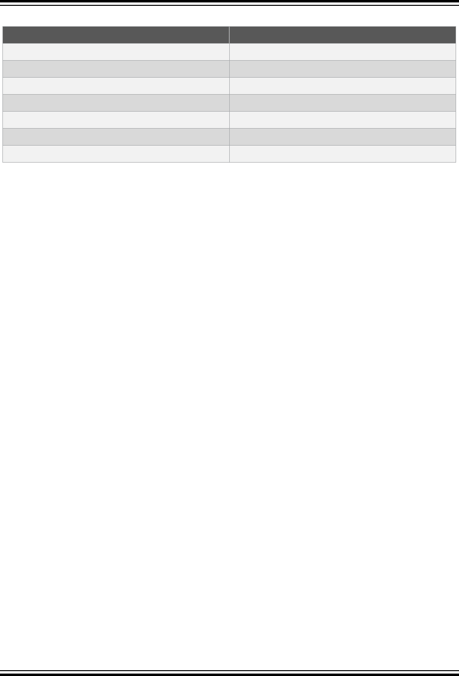
Table 6-3. File Names
Extensions Definition
file.hex
Executable file
file.elf
ELF debug file
file.o
Object file (intermediate file)
file.s
Assembly code file (intermediate file)
file.i
Preprocessed C file (intermediate file)
file.ii
Preprocessed C++ file (intermediate file)
file.map
Map file
The names of many output files use the same base name as the source file from which they were derived. For
example the source file input.c will create an object file called input.o.
The main output file is an ELF file called a.elf, unless you override that name using the -o option.
If you are using an IDE, such as MPLAB X IDE, to specify options to the compiler, there is typically a project file that
is created for each application. The name of this project is used as the base name for project-wide output files, unless
otherwise specified by the user. However check the manual for the IDE you are using for more details.
Note: Throughout this manual, the term project name will refer to the name of the project created in the IDE.
The compiler is able to directly produce a number of the output file formats which are used by Microchip development
tools.
The default behavior of xc32-gcc and xc32-g++ is to produce an ELF output. To make changes to the file’s output
or the file names, see 6.7 Driver Option Descriptions.
6.5.2 Diagnostic Files
Two valuable files produced by the compiler are the assembly list file, produced by the assembler, and the map file,
produced by the linker.
The assembly list file contains the mapping between the original source code and the generated assembly code. It is
useful for information such as how C source was encoded, or how assembly source may have been optimized. It is
essential when confirming if compiler-produced code that accesses objects is atomic, and shows the region in which
all objects and code are placed.
The option to create a listing file in the assembler is -a (or -Wa,-a if passed to the driver). There are many variants
to this option, which may be found in the “MPLAB
®
XC32 Assembler, Linker and Utilities User’s Guide”
(DS50002186). To pass the option from the compiler, see 6.7.9 Options for Assembling.
There is one list file produced for each build. There is one assembler listing file for each translation unit. This is a pre-
link assembler listing so it will not show final addresses. Thus, if you require a list file for each source file, these files
must be compiled separately, see 6.2.2 Multi-Step C Compilation. This is the case if you build using MPLAB IDE.
Each list file will be assigned the module name and extension .lst.
The map file shows information relating to where objects were positioned in memory. It is useful for confirming that
user-defined linker options were correctly processed, and for determining the exact placement of objects and
functions.
The option to create a map file in the linker is -Map file (or -Wl,-Map=file, if passed to the driver), which can be
found in the “MPLAB
®
XC32 Assembler, Linker and Utilities User’s Guide” (DS50002186). To pass the option from
the compiler, see 6.7.10 Options for Linking.
There is one map file produced when you build a project, assuming the linker was executed and ran to completion.
6.6 Compiler Messages
All compiler applications use textual messages to report feedback during the compilation process.
XC32 Compiler for PIC32M
Command-line Driver
© 2020 Microchip Technology Inc.
User Guide
DS50002799B-page 79

There are several types of messages, described below. The behavior of the compiler when encountering a message
of each type is also listed.
Warning
Messages
Indicates source code or other situations that can be compiled, but is unusual and might lead to
runtime failures of the code. The code or situation that triggered the warning should be
investigated; however, compilation of the current module will continue, as will compilation of any
remaining modules.
Error
Messages
Indicates source code that is illegal or that compilation of code cannot take place. Compilation will
be attempted for the remaining source code in the current module (however the cause of the initial
error might trigger further errors) and compilation of the other modules in the project will take
place, but the project will not be linked.
Fatal
Messages
Indicates a situation in which compilation cannot proceed and which forces the compilation
process to stop immediately.
For information on options that control compiler output of errors, warnings or comments, see 6.7.4 Options for
Controlling the C++ Dialect.
6.7 Driver Option Descriptions
Most aspects of the compilation process can be controlled using options passed to the command-line driver, xc32-
gcc.
The GCC compiler on which the MPLAB XC32 C Compiler is based provides many options in addition to those
discussed in this document. It is recommended that you avoid any option that has not been documented here,
especially those that control the generation or optimization of code.
All single letter options are identified by a leading dash character, “-”, for example, -c. Some single letter options
specify an additional data field which follows the option name immediately and without any whitespace, for example,
-Idir. Options are case sensitive, so -c is a different option to -C. All options are identified by single or double
leading dash character, for example, -c or --version.
Use the --help option to obtain a brief description of accepted options on the command line.
If you are compiling from within the MPLAB X IDE, it will issue explicit options to the compiler that are based on the
selections in the project's Project Properties dialog. The default project options might be different to the default
options used by the compiler when running on the command line, so you should review these to ensue that they are
acceptable.
6.7.1 Options Specific to PIC32M Devices
These options are specific to the PIC32M device, not the compiler.
Table 6-4. PIC32M Device-Specific Options
Option Definition
-G num
Put global and static items less than or equal to num bytes into the small data or bss section
instead of the normal data or bss section. This allows the data to be accessed using a single
instruction.
All modules should be compiled with the same -G num value.
-mappio-debug
Enable the APPIN/APPOUT debugging library functions for the Microchip debugger and in-
circuit emulator. This feature allows you to use the DBPRINTF and related functions and
macros as described in the “32-bit Language Tool Libraries” document (DS51685). Enable this
option only when using a target PIC32 device that supports the APPIN/APPOUT feature.
-mcci
Enables the Microchip Common C Interface compilation mode.
XC32 Compiler for PIC32M
Command-line Driver
© 2020 Microchip Technology Inc.
User Guide
DS50002799B-page 80

...........continued
Option Definition
-mcheck-zero-
division
-mno-check-
zero-division
Trap (do not trap) on integer division by zero. The default is -mcheck-zero-division.
-membedded-
data
-mno-embedded-
data
Allocate variables to the read-only data section first if possible, then next in the small data
section if possible, otherwise in data. This gives slightly slower code than the default, but
reduces the amount of RAM required when executing, and thus may be preferred for some
embedded systems.
-mframe-
header-opt
Allows the compiler to omit a few instructions for each function that does not use its incoming
frame header. This feature usually improves both execution speed and code size.
-mgen-pie-
static
Generate position-independent code suitable for statically linking into a Position-Independent
Executable (PIE). Such code access all constant addresses through a Global Offset Table
(GOT). A special ELF loader, running on the target device, resolves the GOT entries and loads
the final executable image into memory. Pass this option to the xc32-gcc compilation driver
when compiling, assembling, and linking.
-mno-hi-addr-
opt
The Special Function Register (SFR) Access Efficiency feature adds the address attribute to
Peripheral SFRs defined in the processor header file. With this added information, a new
compiler optimization reduces the number of registers required to access multiple SFRs within
a single function. This also allows the compiler to remove redundant load instructions. Enabled
by default at optimization levels -O2, -Os, & -O3.
Note: If you are building a static library that accesses an SFR and you want that same
prebuilt library to work across devices that may have the SFRs located at a different address
(for example TMR1 is at different addresses on device A and device B), compile your library
with the -mno-hi-addr-opt option. This will result in larger code, but the SFR address will
be determined at link time.
-minterlink-
compressed
Generate code that is link compatible with MIPS16 and microMIPS code.
-mips16
-mno-mips16
Generate (do not generate) MIPS16 code. This is only available in the PRO edition.
Note: On PIC32M devices, bit 0 of the program counter indicates the Instruction Set
Architecture (ISA) mode. When this bit is clear, the device is running in MIPS32 mode. When
this bit is set, the device is running in either MIPS16 or microMIPS mode, depending on the
device core. This means that if you execute a hard-coded jump, bit 0 must be set to the
appropriate value for your target function. Hard-coded jumps are most commonly seen when
jumping from a bootloader to a bootloaded application.
-mjals
-mno-jals
Generate (do not generate) 'jals' for microMIPS by recognizing that the branch delay slot
instruction can be 16 bits. This implies that the function call cannot switch the current mode
during the linking stage because we don't have 'jals' that supports 16-bit branch delay slot
instructions. You man need to use -mno-jals if you have link errors when attempting to link a
microMIPS object/library with a MIPS32 object/library.
-mlong-calls
-mno-long-
calls
Disable (do not disable) use of the jal instruction. Calling functions using jal is more efficient
but requires the caller and callee to be in the same 256 megabyte segment. This option has no
effect on abicalls code. The default is -mno-long-calls.
-mmemcpy
-mno-memcpy
Force (do not force) the use of memcpy() for non-trivial block moves. The default is -mno-
memcpy, which allows GCC to inline most constant-sized co-pies.
XC32 Compiler for PIC32M
Command-line Driver
© 2020 Microchip Technology Inc.
User Guide
DS50002799B-page 81

...........continued
Option Definition
-mmicromips
-mno-micromips
Generate (do not generate) microMIPS
™
instructions. This feature is available only in the PRO
edition.
When your device is configured to boot to the microMIPS compressed ISA mode (for
example,#pragma config BOOTISA=MICROMIPS), use the -mmicromips option when
linking to specify the microMIPS startup code.
Note: On PIC32M devices, bit 0 of the program counter indicates the Instruction Set
Architecture (ISA) mode. When this bit is clear, the device is running in MIPS32 mode. When
this bit is set, the device is running in either MIPS16 or microMIPS mode, depending on the
device core. This means that if you execute a hard-coded jump, bit 0 must be set to the
appropriate value for your target function. Hard-coded jumps are most commonly seen when
jumping from a bootloader to a bootloaded application.
-mno-float
Do not use software floating-point libraries.
-mno-
peripheral-
libs
-mno-peripheral-libs is now the default. -mperipheral-libs is optional. By default,
the peripheral libraries are linked specified via the device-specific linker script. Do not use the
standard peripheral libraries when link-ing.
-mprocessor
Selects the device for which to compile.
(for example,-mprocessor=32MX360F512L)
-mreserve
When building a project for debugging in MPLAB X IDE, the IDE passes the -mreserve
option to the toolchain in order to reserve memory for use by the debug executive. This
mechanism replaces the hard-coded reserved memory regions in the linker script.
-msmart-io=[0|
1|2]
This option attempts to statically analyze format strings passed to printf, scanf and the 'f'
and 'v' variations of these functions. Uses of nonfloating-point format arguments will be
converted to use an integer-only variation of the library function. For many applications, this
feature can reduce program-memory usage.
-msmart-io=0 disables this option, while -msmart-io=2 causes the compiler to be
optimistic and convert function calls with variable or unknown format arguments. -msmart-
io=1 is the default and will convert only when the compiler can prove that floating-point
support is not required.
-mtext="scn-
name"
Places text (program code) to be placed in a section named "scn-name", rather than the
default .text section. No white space should appear around the '='. This command can be
useful when developing a bootloader and you want to map your code in a custom linker script.
Example:
xc32-gcc bootloader.c
-mtext="MySectionName,address(0x9D00a000)"
-mprocessor=32MX795F512L
-muninit-
const-in-
rodata
-mno-uninit-
const-in-
rodata
Put uninitialized const variables in the read-only data section. This option is only meaningful
in conjunction with -membedded-data.
--nofallback
Require an MPLAB XC32 Pro license and do not fall back to a lesser license.
6.7.2 Options for Controlling the Kind of Output
The following options control the kind of output produced by the compiler.
XC32 Compiler for PIC32M
Command-line Driver
© 2020 Microchip Technology Inc.
User Guide
DS50002799B-page 82

Table 6-5. Kind-of-Output Control Options
Option Definition
-c
Compile or assemble the source files, but do not link. The default file extension is .o.
-E
Stop after the preprocessing stage (that is, before running the compiler proper). The default
output file is stdout.
-fexceptions
Enable exception handling. You may need to enable this option when compiling C code that
needs to interoperate properly with exception handlers written in C++.
-o file
Place the output in file.
-S
Stop after compilation proper (that is, before invoking the assembler). The default output file
extension is .s.
-v
Print the commands executed during each stage of compilation.
-x
You can specify the input language explicitly with the -x option:
-x language
Specify explicitly the language for the following input files (rather than letting the compiler choose
a default based on the file name suffix). This option applies to all following input files until the next
-x option. The following values are supported by the compiler:
c
c++
c-header
cpp-output
assembler
assembler-with-cpp
-x none
Turn off any specification of a language, so that subsequent files are handled according to their
file name suffixes. This is the default -behavior but is needed if another -x option has been used.
For exam-ple:
xc32-gcc -x assembler foo.asm bar.asm -x none main.c mabonga.s
Without the -xnone, the compiler assumes all the input files are for the assembler.
--help
Print a description of the command line options.
6.7.3 Options for Controlling the C Dialect
The following options define the kind of C dialect used by the compiler.
Table 6-6. C Dialect Control Options
Option Definition
-ansi
Support all (and only) ANSI-standard C programs.
XC32 Compiler for PIC32M
Command-line Driver
© 2020 Microchip Technology Inc.
User Guide
DS50002799B-page 83

...........continued
Option Definition
-aux-info filename
Output to the given filename prototyped declarations for all functions declared and/or
defined in a translation unit, including those in header files. This option is silently
ignored in any language other than C. Besides declarations, the file indicates, in
comments, the origin of each declaration (source file and line), whether the declaration
was implicit, prototyped or unprototyped (I, N for new or O for old, respectively, in the
first character after the line number and the colon), and whether it came from a
declaration or a definition (C or F, respectively, in the following character). In the case
of function definitions, a K&R-style list of arguments followed by their declarations is
also provided, inside comments, after the declaration.
-fcheck-new / -fno-
check-new (default)
Check that the pointer returned by operator new is non-null.
-fenforce-eh-specs
(default) / -fno-
enforce-eh-specs
Generate/Do not generate code to check for violation of exception specifications at
runtime. The -fno-enforce-eh-specs option violates the C++ standard, but may
be useful for reducing code size in production builds, much like defining 'NDEBUG'.
This does not give user code permission to throw exceptions in violation of the
exception specifications; the compiler will still optimize based on the specifications, so
throwing an unexpected exception will result in undefined behavior.
-ffreestanding
Assert that compilation takes place in a freestanding en-vironment. This implies -fno-
builtin. A freestanding environment is one in which the standard library may not
exist, and program start-up may not necessarily be at main. The most obvious
example is an OS kernel. This is equivalent to -fno-hosted.
-fno-asm
Do not recognize asm, inline or typeof as a keyword, so that code can use these
words as identifiers. You can use the keywords _ _asm_ _, _ _inline_ _ and _
_typeof_ _ instead.
-ansi implies -fno-asm.
-fno-builtin
-fno-builtin-
function
Don’t recognize built-in functions that do not begin with _ _builtin_ as prefix.
-fno-exceptions
Disable C++ exception handling. This option disables the generation of extra code
needed to propagate exceptions.
-fno-rtti
Enable/Disable runtime type-identification features. The -fno-rtti option disables
generation of information about every class with virtual functions for use by the C++
runtime type identification features ('dynamic_cast' and 'typeid'). If you don't use
those parts of the language, you can save some space by using this flag. Note that
exception handling uses the same information, but it will generate it as needed. The
'dynamic_cast' operator can still be used for casts that do not require runtime type
information, that is, casts to void * or to unambiguous base classes.
-fsigned-char
Let the type char be signed, like signed char.
(This is the default.)
XC32 Compiler for PIC32M
Command-line Driver
© 2020 Microchip Technology Inc.
User Guide
DS50002799B-page 84

...........continued
Option Definition
-fsigned-bitfields
-funsigned-
bitfields
-fno-signed-
bitfields
-fno-unsigned-
bitfields
These options control whether a bit field is signed or unsigned, when the declaration
does not use either signed or unsigned. By default, such a bit field is signed, unless -
traditional is used, in which case bit fields are always unsigned.
-funsigned-char
Let the type char be unsigned, like unsigned char.
6.7.4 Options for Controlling the C++ Dialect
The following options define the kind of C++ dialect used by the compiler.
Table 6-7. C++ Dialect Control Options
Option Definition
-ansi
Support all (and only) ANSI-standard C++ programs.
-aux-info filename
Output to the given filename prototyped declarations for all functions declared and/or
defined in a translation unit, including those in header files. This option is silently
ignored in any language other than C++. Besides declarations, the file indicates, in
comments, the origin of each declaration (source file and line), whether the
declaration was implicit, prototyped or unprototyped (I, N for new or O for old,
respectively, in the first character after the line number and the colon), and whether it
came from a -declaration or a definition (C or F, respectively, in the -following
character). In the case of function definitions, a K&R-style list of arguments followed
by their declarations is also provided, inside comments, after the declaration.
-ffreestanding
Assert that compilation takes place in a freestanding en-vironment. This implies -
fno-builtin. A freestanding environment is one in which the standard library may
not exist, and program start-up may not necessarily be at main. The most obvious
example is an OS kernel. This is equivalent to -fno-hosted.
-fno-asm
Do not recognize asm, inline or typeof as a keyword, so that code can use these
words as identifiers. You can use the keywords _ _asm_ _, _ _inline_ _ and _
_typeof_ _ instead.
-ansi implies -fno-asm.
-fno-builtin
-fno-builtin-
function
Don’t recognize built-in functions that do not begin with _ _builtin_ as prefix.
-fsigned-char
Let the type char be signed, like signed char.
(This is the default.)
-fsigned-bitfields
-funsigned-bitfields
-fno-signed-
bitfields
-fno-unsigned-
bitfields
These options control whether a bit field is signed or unsigned, when the declaration
does not use either signed or unsigned. By default, such a bit field is signed, unless -
traditional is used, in which case bit fields are always unsigned.
-funsigned-char
Let the type char be unsigned, like unsigned char.
XC32 Compiler for PIC32M
Command-line Driver
© 2020 Microchip Technology Inc.
User Guide
DS50002799B-page 85

6.7.5 Options for Controlling Warning and Errors
Warnings are diagnostic messages that report constructions that are not inherently erroneous, but that are risky or
suggest there may have been an error.
You can request many specific warnings with options beginning -W; for example, -Wimplicit, to request warnings
on implicit declarations. Each of these specific warning options also has a negative form beginning -Wno- to turn off
warnings; for example, -Wno-implicit. This manual lists only one of the two forms, whichever is not the default.
The following options control the amount and kinds of warnings produced by the compiler.
Table 6-8. Warning and Error Options Implied by All Warnings
Option Definition
-fsyntax-only
Check the code for syntax, but don’t do anything beyond that.
-pedantic
Issue all the warnings demanded by strict ANSI C. Reject all programs that use forbidden
extensions.
-pedantic-errors
Like -pedantic, except that errors are produced rather than warnings.
-w
Inhibit all warning messages.
-Wall
This enables all the warnings about constructions that some users consider questionable
and that are easy to avoid (or modify to prevent the warning), even in conjunction with
macros.
Note that some warning flags are not implied by -Wall. Some of them warn about
constructions that users generally do not consider questionable, but which occasionally
you might wish to check for; others warn about constructions that are necessary or hard
to avoid in some cases, and there is no simple way to modify the code to suppress the
warning. Some of them are enabled by -Wextra but many of them must be enabled
individually.
-Waddress
Warn about suspicious uses of memory addresses. These include using the address of a
function in a conditional expression, such as void func(void); if (func), and
comparisons against the memory address of a string literal, such as if (x == "abc").
Such uses typically indicate a programmer error: the address of a function always
evaluates to true, so their use in a conditional usually indicates that the programmer
forgot the parentheses in a function call; and comparisons against string literals result in
unspecified behavior and are not portable in C, so they usually indicate that the
programmer intended to use strcmp.
-Wchar-subscripts
Warn if an array subscript has type char.
-Wcomment
Warn whenever a comment-start sequence /* appears in a /*comment, or whenever a
Backslash-Newline appears in a // comment.
-Wdiv-by-zero
Warn about compile-time integer division by zero. To inhibit the warning messages, use -
Wno-div-by-zero. Floating-point division by zero is not warned about, as it can be a -
legitimate way of obtaining infinities and NaNs.
This is the default.
-Wformat
Check calls to printf and scanf, etc., to make sure that the arguments supplied have
types appropriate to the format string specified.
-Wimplicit
Equivalent to specifying both -Wimplicit-int and -Wimplicit-function-
declaration.
-Wimplicit-
function-
declaration
Give a warning whenever a function is used before being declared.
-Wimplicit-int
Warn when a declaration does not specify a type.
XC32 Compiler for PIC32M
Command-line Driver
© 2020 Microchip Technology Inc.
User Guide
DS50002799B-page 86

...........continued
Option Definition
-Wmain
Warn if the type of main is suspicious. main should be a function with external linkage,
returning int, taking either zero, two, or three arguments of appropriate types.
-Wmissing-braces
Warn if an aggregate or union initializer is not fully bracketed. In the following example,
the initializer for a is not fully bracketed, but that for b is fully bracketed.
int a[2][2] = { 0, 1, 2, 3 };
int b[2][2] = { { 0, 1 }, { 2, 3 } };
-Wno-multichar
Warn if a multi-character character constant is used. Usually, such constants are
typographical errors. Since they have implementation-defined values, they should not be
used in portable code. The following example illustrates the use of a multi-character
character constant:
char
xx(void)
{
return('xx');
}
-Wparentheses
Warn if parentheses are omitted in certain contexts, such as when there is an assignment
in a context where a truth value is expected, or when operators are nested whose
precedence people often find confusing.
-Wreturn-type
Warn whenever a function is defined with a return-type that defaults to int. Also warn
about any return statement with no return-value in a function whose return-type is not
void.
-Wsequence-point
Warn about code that may have undefined semantics because of violations of sequence
point rules in the C standard.
The C standard defines the order in which expressions in a C program are evaluated in
terms of sequence points, which represent a partial ordering between the execution of
parts of the program: those executed before the sequence point and those executed after
it. These occur after the evaluation of a full expression (one which is not part of a larger
expression), after the evaluation of the first operand of a &&, ||, ? : or , (comma)
operator, before a function is called (but after the evaluation of its arguments and the
expression denoting the called function), and in certain other places. Other than as
expressed by the sequence point rules, the order of evaluation of subexpressions of an
expression is not specified. All these rules describe only a partial order rather than a total
order. For example, if two functions are called within one expression with no sequence
point between them, the order in which the functions are called is not specified. However,
the standards committee has ruled that function calls do not overlap.
It is not specified when between sequence points modifications to the values of objects
take effect. Programs whose behavior depends on this have undefined behavior. The C
standard specifies that “Between the previous and next sequence point, an object shall
have its stored value modified, at most once, by the evaluation of an expression.
Furthermore, the prior value shall be read only to determine the value to be stored.” If a
program breaks these rules, the results on any particular implementation are entirely
unpredictable.
Examples of code with undefined behavior are a = a++;,
a[n] = b[n++] and a[i++] = i;. Some more complicated cases are not diagnosed
by this option and it may give an occasional false positive result, but in general it has
been found fairly effective at detecting this sort of problem in programs.
XC32 Compiler for PIC32M
Command-line Driver
© 2020 Microchip Technology Inc.
User Guide
DS50002799B-page 87

...........continued
Option Definition
-Wswitch
Warn whenever a switch statement has an index of enumeral type and lacks a case for
one or more of the named codes of that enumeration. (The presence of a default label
prevents this warning.) case labels outside the enumeration range also provoke warnings
when this option is used.
-Wsystem-headers
Print warning messages for constructs found in system header files. Warnings from
system headers are normally suppressed on the assumption that they usually do not
indicate real problems and would only make the compiler output harder to read. Using
this command line option tells the compiler to emit warnings from system headers as if
they occurred in user code. However, note that using -Wall in conjunction with this
option does not warn about unknown pragmas in system headers. For that, -Wunknown-
pragmas must also be used.
-Wtrigraphs
Warn if any trigraphs are encountered (assuming they are enabled).
-Wuninitialized
Warn if an automatic variable is used without first being initialized.
These warnings are possible only when optimization is enabled, because they require
data flow information that is computed only when optimizing.
These warnings occur only for variables that are candidates for register allocation.
Therefore, they do not occur for a variable that is declared volatile, or whose address
is taken, or whose size is other than 1, 2, 4 or 8 bytes. Also, they do not occur for
structures, unions or arrays, even when they are in registers.
Note that there may be no warning about a variable that is used only to compute a value
that itself is never used, because such computations may be deleted by data flow
analysis before the warnings are printed.
-Wunknown-pragmas
Warn when a #pragma directive is encountered which is not understood by the compiler.
If this command line option is used, warnings will even be issued for unknown pragmas in
system header files. This is not the case if the warnings were only enabled by the -Wall
command line option.
-Wunused
Warn whenever a variable is unused aside from its declaration, whenever a function is
declared static but never defined, whenever a label is declared but not used, and
whenever a statement computes a result that is explicitly not used.
In order to get a warning about an unused function parameter, both -W and -Wunused
must be specified.
Casting an expression to void suppresses this warning for an expression. Similarly, the
unused attribute suppresses this warning for unused variables, parameters and labels.
-Wunused-function
Warn whenever a static function is declared but not defined or a non-inline static function
is unused.
-Wunused-label
Warn whenever a label is declared but not used. To suppress this warning, use the
unused attribute.
-Wunused-
parameter
Warn whenever a function parameter is unused aside from its declaration. To suppress
this warning, use the unused attribute.
-Wunused-variable
Warn whenever a local variable or non-constant static variable is unused aside from its
declaration. To suppress this warning, use the unused attribute.
-Wunused-value
Warn whenever a statement computes a result that is explicitly not used. To suppress this
warning, cast the expression to void.
The following -W options are not implied by -Wall. Some of them warn about constructions that users generally do
not consider questionable, but which you might occasionally wish to check for. Others warn about constructions that
XC32 Compiler for PIC32M
Command-line Driver
© 2020 Microchip Technology Inc.
User Guide
DS50002799B-page 88

are necessary or hard to avoid in some cases, and there is no simple way to modify the code to suppress the
warning.
Table 6-9. Warning and Error Options Not Implied by All Warnings
Option Definition
-W
Print extra warning messages for these events:
• A nonvolatile automatic variable might be changed by a call to longjmp. These
warnings are possible only in optimizing compilation. The compiler sees only the calls
to setjmp. It cannot know where longjmp will be called. In fact, a signal handler
could call it at any point in the code. As a result, a warning may be generated even
when there is in fact no problem, because longjmp cannot in fact be called at the
place that would cause a problem.
• A function could exit both via return value; and return;. Completing the
function body without passing any return statement is treated as return;.
• An expression-statement or the left-hand side of a comma expression contains no
side effects. To suppress the warning, cast the unused expression to void. For
example, an expression such as x[i,j] causes a warning, but x[(void)i,j]
does not.
• An unsigned value is compared against zero with < or <=.
• A comparison like x<=y<=z appears, This is equivalent to (x<=y ? 1 : 0) <= z,
which is a different interpretation from that of ordinary mathematical notation.
• Storage-class specifiers like static are not the first things in a declaration.
According to the C Standard, this usage is obsolescent.
• If -Wall or -Wunused is also specified, warn about unused arguments.
• A comparison between signed and unsigned values could produce an incorrect result
when the signed value is converted to unsigned (but don’t warn if -Wno-sign-
compare is also specified).
• An aggregate has a partly bracketed initializer. For example, the following code would
evoke such a warning, because braces are missing around the initializer for x.h:
struct s { int f, g; };
struct t { struct s h; int i; };
struct t x = { 1, 2, 3 };
• An aggregate has an initializer that does not initialize all members. For example, the
following code would cause such a warning, because x.h would be implicitly -
initialized to zero:
struct s { int f, g, h; };
struct s x = { 3, 4 };
-Waggregate-
return
Warn if any functions that return structures or unions are defined or called.
-Wbad-function-
cast
Warn whenever a function call is cast to a non-matching type. For example, warn if int
foof() is cast to anything *.
-Wcast-align
Warn whenever a pointer is cast, such that the required alignment of the target is
increased. For example, warn if a char * is cast to an int *.
-Wcast-qual
Warn whenever a pointer is cast, so as to remove a type qualifier from the target type. For
example, warn if a const char * is cast to an ordinary char *.
XC32 Compiler for PIC32M
Command-line Driver
© 2020 Microchip Technology Inc.
User Guide
DS50002799B-page 89

...........continued
Option Definition
-Wconversion
Warn if a prototype causes a type conversion that is different from what would happen to
the same argument in the absence of a prototype. This includes conversions of fixed point
to floating and vice versa, and conversions changing the width or signedness of a fixed
point argument, except when the same as the default promotion.
Also, warn if a negative integer constant expression is implicitly converted to an unsigned
type. For example, warn about the assignment x = -1 if x is unsigned. But do not warn
about explicit casts like (unsigned) -1.
-Werror
Make all warnings into errors.
-Winline
Warn if a function can not be inlined, and either it was declared as inline, or else the -
finline-functions option was given.
-Wlarger-than-len
Warn whenever an object of larger than len bytes is defined.
-Wlong-long
-Wno-long-long
Warn if long long type is used. This is default. To inhibit the warning messages, use -
Wno-long-long. Flags -Wlong-long and -Wno-long-long are taken into account
only when -pedantic flag is used.
-Wmissing-
declarations
Warn if a global function is defined without a previous declaration. Do so even if the
definition itself provides a -prototype.
-Wmissing-
format-attribute
If -Wformat is enabled, also warn about functions that might be candidates for format
attributes. Note these are only possible candidates, not absolute ones. This option has no
effect unless -Wformat is enabled.
-Wmissing-
noreturn
Warn about functions that might be candidates for attribute noreturn. These are only
possible candidates, not absolute ones. Care should be taken to manually verify functions.
In fact, do not ever return before adding the noreturn attribute, otherwise subtle code
generation bugs could be introduced.
-Wmissing-
prototypes
Warn if a global function is defined without a previous prototype declaration. This warning
is issued even if the definition itself provides a prototype (this option can be used to detect
global functions that are not declared in header files).
-Wnested-externs
Warn if an extern declaration is encountered within a function.
-Wno-deprecated-
declarations
Do not warn about uses of functions, variables and types marked as deprecated by using
the deprecated attribute.
-Wpadded
Warn if padding is included in a structure, either to align an element of the structure or to
align the whole structure.
-Wpointer-arith
Warn about anything that depends on the size of a function type or of void. The compiler
assigns these types a size of 1, for convenience in calculations with void *pointers and
pointers to functions.
-Wredundant-decls
Warn if anything is declared more than once in the same scope, even in cases where
multiple declaration is valid and changes nothing.
-Wshadow
Warn whenever a local variable shadows another local variable.
-Wsign-compare
-Wno-sign-compare
Warn when a comparison between signed and unsigned values could produce an
incorrect result when the signed value is converted to unsigned. This warning is also
enabled by -W. To get the other warnings of -W without this warning, use -W -Wno-sign-
compare.
-Wstrict-
prototypes
Warn if a function is declared or defined without specifying the argument types (an old-
style function definition is permitted without a warning if preceded by a declaration which
specifies the argument types).
XC32 Compiler for PIC32M
Command-line Driver
© 2020 Microchip Technology Inc.
User Guide
DS50002799B-page 90

...........continued
Option Definition
-Wtraditional
Warn about certain constructs that behave differently in traditional and ANSI C.
• Macro arguments occurring within string constants in the macro body. These would
substitute the argument in traditional C, but are part of the constant in ANSI C.
• A function declared external in one block and then used after the end of the block.
• A switch statement has an operand of type long.
• A nonstatic function declaration follows a static one. This construct is not accepted by
some traditional C compilers.
-Wundef
Warn if an undefined identifier is evaluated in an #if -directive.
-Wwrite-strings
Give string constants the type const char[length] so that copying the address of one
into a non-const char * pointer gets a warning. At compile time, these warnings help you
find code that you can try to write into a string constant, but only if you have been very
careful about using const in declarations and prototypes. Otherwise, it’s just a nuisance,
which is why -Wall does not request these warnings.
6.7.6 Options for Debugging
The following options are used for debugging.
Table 6-10. Debugging Options
Option Definition
-g
Produce debugging information.
The compiler supports the use of -g with -O making it possible to debug optimized code. The
shortcuts taken by optimized code may occasionally produce surprising results:
• Some declared variables may not exist at all
• Flow of control may briefly move unexpectedly
• Some statements may not be executed because they compute constant results or their
values were already at hand
• Some statements may execute in different places because they were moved out of loops
Nevertheless it proves possible to debug optimized output. This makes it reasonable to use the
optimizer for programs that might have bugs.
-Q
Makes the compiler print out each function name as it is compiled, and print some statistics
about each pass when it finishes.
-save-temps
-save-
temps=cwd
Don’t delete intermediate files. Place them in the current directory and name them based on the
source file. Thus, compiling foo.c with -c -save-temps would produce the following files:
foo.i (preprocessed file)
foo.s (assembly language file)
foo.o (object file)
XC32 Compiler for PIC32M
Command-line Driver
© 2020 Microchip Technology Inc.
User Guide
DS50002799B-page 91

...........continued
Option Definition
-save-
temps=obj
Similar to -save-temps=cwd, but if the -o option is specified, the temporary files are based on
the object file. If the -o option is not specified, the -save-temps=obj switch behaves like –
save-temps.
For example:
xc32-gcc -save-temps=obj -c
foo.c
xc32-gcc -save-temps=obj -c bar.c -o
dir/xbar.o
xc32-gcc -save-temps=obj foobar.c -o
dir2/yfoobar
would create foo.i, foo.s, dir/xbar.i, dir/xbar.s, dir2/yfoobar.i, dir2/
yfoobar.s, and dir2/yfoobar.o.
6.7.7 Options for Controlling Optimization
The following options control compiler optimizations.
Table 6-11. General Optimization Options
Option Edition Definition
-O0
All Do not optimize (this is the default).
Without -O, the compiler’s goal is to reduce the cost of compilation and to make
debugging produce the expected results. Statements are independent: if you stop the
program with a breakpoint between statements, you can then assign a new value to any
variable or change the program counter to any other statement in the function and get
exactly the results you would expect from the source code.
The compiler only allocates variables declared register in registers.
-O
-O1
All Optimization level 1. Optimizing compilation takes somewhat longer and a lot more host
memory for a large function.
With -O, the compiler tries to reduce code size and execution time.
When -O is specified, the compiler turns on -fthread-jumps and
-fdefer-pop. The compiler turns on-fomit-frame-pointer.
-O2
PRO Optimization level 2. The compiler performs nearly all supported optimizations that do not
involve a space-speed trade-off. -O2 turns on all optional -optimizations except for loop
unrolling (-funroll-loops), function inlining (-finline-functions), and strict
aliasing optimizations (-fstrict-aliasing). It also turns on force copy of memory
operands (-fforce-mem) and Frame Pointer elimination (-fomit-frame-pointer).
As compared to -O, this option increases both compilation time and the performance of
the generated code.
-O3
PRO Optimization level 3. -O3 turns on all optimizations specified by -O2 and also turns on the
inline-functions option.
-Os
PRO Optimize for size. -Os enables all -O2 optimizations that do not typically increase code
size. It also performs further optimizations designed to reduce code size.
XC32 Compiler for PIC32M
Command-line Driver
© 2020 Microchip Technology Inc.
User Guide
DS50002799B-page 92

...........continued
Option Edition Definition
-flto
PRO This option runs the standard link-time optimizer. When invoked with source code, the
compiler adds an internal bytecode representation of the code to special sections in the
object file. When the object files are linked together, all the function bodies are read from
these sections and instantiated as if they had been part of the same translation unit.
To use the link-time optimizer, specify -flto both at compile time and during the final
link. For example:
xc32-gcc -c -O1 -flto -mprocessor=32MX795F512L foo.c
xc32-gcc -c -O1 -flto -mprocessor=32MX795F512L bar.c
xc32-gcc -o myprog.elf -flto -O3 -mprocessor=32MX795F512L foo.o
bar.o
Another (simpler) way to enable link-time optimization is,
xc32-gcc -o myprog.elf -flto -O3 -mprocessor=32MX795F512L foo.c
bar.c
Link time optimizations do not require the presence of the whole program to operate. If
the program does not require any symbols to be exported, it is possible to combine -
flto with -fwhole-program to allow the interprocedural optimizers to use more
aggressive assumptions which may lead to improved optimization opportunities.
Regarding portability: The bytecode files are versioned and there is a strict version check,
so bytecode files generated in one version of XC32 may not work with an older/newer
version of the XC32 compiler.
-ftoplevel
-reorder
All Allow reordering top-level functions, variables, and asm statements. They may not be
output in the same order that they appear in the input file. This option also allows removal
of unreferenced static variables. Use this options with optimization level -01 or greater.
-fwhole -
program
PRO Assume that the current compilation unit represents the whole program being compiled.
All public functions and variables, with the exception of main and those merged by
attribute externally_visible, become static functions and in effect are optimized
more aggressively by interprocedural optimizers. While this option is equivalent to proper
use of the static keyword for programs consisting of a single file, in combination with
option -flto, this flag can be used to compile many smaller scale programs since the
functions and variables become local for the whole combined compilation unit, not for the
single source file itself.
The following options control specific optimizations. The -O2 option turns on all of these optimizations except -
funroll-loops, -funroll-all-loops and -fstrict-aliasing.
You can use the following flags in the rare cases when “fine-tuning” of optimizations to be performed is desired.
Table 6-12. Specific Optimization Options
Option Definition
-falign-functions
-falign-functions=n
Align the start of functions to the next power-of-two greater than n, skipping up to n
bytes. For instance, -falign-functions=32 aligns functions to the next 32-byte
boundary, but -falign-functions=24 would align to the next 32-byte boundary only
if this can be done by skipping 23 bytes or less.
-fno-align-functions and -falign-functions=1 are equivalent and mean that
functions are not aligned.
The assembler only supports this flag when n is a power of two, so n is rounded up. If n
is not specified, use a machine-dependent default.
XC32 Compiler for PIC32M
Command-line Driver
© 2020 Microchip Technology Inc.
User Guide
DS50002799B-page 93
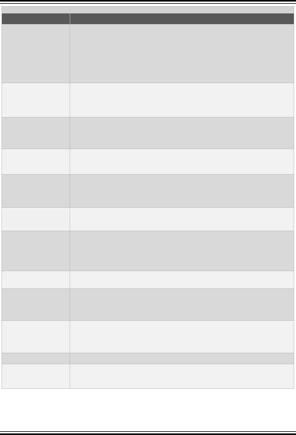
...........continued
Option Definition
-falign-labels
-falign-labels=n
Align all branch targets to a power-of-two boundary, skipping up to n bytes like -
falign-functions. This option can easily make code slower, because it must insert
dummy operations for when the branch target is reached in the usual flow of the code.
If -falign-loops or -falign-jumps are applicable and are greater than this value,
then their values are used instead.
If n is not specified, use a machine-dependent default which is very likely to be 1,
meaning no alignment.
-falign-loops
-falign-loops=n
Align loops to a power-of-two boundary, skipping up to n bytes like -falign-
functions. The hope is that the loop is executed many times, which makes up for any
execution of the dummy operations.
If n is not specified, use a machine-dependent default.
-fcaller-saves
Enable values to be allocated in registers that are -clobbered by function calls, by
emitting extra instructions to save and restore the registers around such calls. Such
allocation is done only when it seems to result in better code than would otherwise be
produced.
-fcse-follow-jumps
In common subexpression elimination, scan through jump instructions when the target
of the jump is not reached by any other path. For example, when CSE encounters an if
statement with an else clause, CSE follows the jump when the condition tested is false.
-fcse-skip-blocks
This is similar to -fcse-follow-jumps, but causes CSE to follow jumps which
conditionally skip over blocks. When CSE encounters a simple if statement with no
else clause, -fcse-skip-blocks causes CSE to follow the jump around the body of
the if.
-fexpensive-
optimizations
Perform a number of minor optimizations that are relatively expensive.
-ffunction-sections
-fdata-sections
Place each function or data item into its own section in the output file. The name of the
function or the name of the data item determines the section's name in the output file.
Only use these options when there are significant benefits for doing so. When you
specify these options, the assembler and linker may create larger object and executable
files and is also slower.
-fgcse
Perform a global common subexpression elimination pass. This pass also performs
global constant and copy propagation.
-fgcse-lm
When -fgcse-lm is enabled, global common subexpression elimination attempts to
move loads which are only killed by stores into themselves. This allows a loop
containing a load/store sequence to change to a load outside the loop, and a copy/store
within the loop.
-fgcse-sm
When -fgcse-sm is enabled, a store motion pass is run after global common
subexpression elimination. This pass attempts to move stores out of loops. When used
in conjunction with -fgcse-lm, loops containing a load/store sequence can change to
a load before the loop and a store after the loop.
-fmove-all-movables
Forces all invariant computations in loops to be moved outside the loop.
-fno-defer-pop
Always pop the arguments to each function call as soon as that function returns. The
compiler normally lets arguments accumulate on the stack for several function calls and
pops them all at once.
XC32 Compiler for PIC32M
Command-line Driver
© 2020 Microchip Technology Inc.
User Guide
DS50002799B-page 94
...........continued
Option Definition
-fno-peephole
-fno-peephole2
Disable machine specific peephole optimizations. Peephole optimizations occur at
various points during the compilation. -fno-peephole disables peephole optimization
on machine instructions, while -fno-peephole2 disables high level peephole
optimizations. To disable peephole entirely, use both options.
-foptimize-
register-move
-fregmove
Attempt to reassign register numbers in move instructions and as operands of other
simple instructions in order to maximize the amount of register tying.
-fregmove and -foptimize-register-moves are the same optimization.
-freduce-all-givs
Forces all general-induction variables in loops to be strength reduced.
These options may generate better or worse code. Results are highly dependent on the
structure of loops within the source code.
-frename-registers
Attempt to avoid false dependencies in scheduled code by making use of registers left
over after register allocation. This optimization most benefits processors with lots of
registers. It can, however, make debugging impossible, since variables no longer stay in
a “home register.”
-frerun-cse-after-
loop
Rerun common subexpression elimination after loop optimizations has been performed.
-frerun-loop-opt
Run the loop optimizer twice.
-fschedule-insns
Attempt to reorder instructions to eliminate instruction stalls due to required data being
unavailable.
-fschedule-insns2
Similar to -fschedule-insns, but requests an additional pass of instruction
scheduling after register allocation has been done.
-fstrength-reduce
Perform the optimizations of loop strength reduction and elimination of iteration
variables.
XC32 Compiler for PIC32M
Command-line Driver
© 2020 Microchip Technology Inc.
User Guide
DS50002799B-page 95

...........continued
Option Definition
-fstrict-aliasing
Allows the compiler to assume the strictest aliasing rules applicable to the language
being compiled. For C, this activates optimizations based on the type of expressions. In
particular, an object of one type is assumed never to reside at the same address as an
object of a different type, unless the types are almost the same. For example, an
unsigned int can alias an int, but not a void* or a double. A character type may
alias any other type.
Pay special attention to code like this:
union a_union {
int i;
double d;
};
int f() {
union a_union t;
t.d = 3.0;
return t.i;
}
The practice of reading from a different union member than the one most recently
written to (called “type-punning”) is common. Even with -fstrict-aliasing, type-
punning is allowed, provided the memory is accessed through the union type. The code
above works as expected. However, this code might not:
int f() {
a_union t;
int* ip;
t.d = 3.0;
ip = &t.i;
return *ip;
}
-fthread-jumps
Perform optimizations where a check is made to see if a jump branches to a location
where another comparison subsumed by the first is found. If so, the first branch is
redirected to either the destination of the second branch or a point immediately following
it, depending on whether the condition is known to be true or false.
-funroll-loops
Perform the optimization of loop unrolling. This is only done for loops whose number of
iterations can be determined at compile time or run time. -funroll-loops implies
both -fstrength-reduce and -frerun-cse-after-loop.
-funroll-all-loops
Perform the optimization of loop unrolling. This is done for all loops and usually makes
programs run more slowly. -funroll-all-loops implies -fstrength-reduce, as
well as -frerun-cse-after-loop.
-fuse-caller-save
Allows the compiler to use the caller-save register model. When combined with inter-
procedural optimizations, the compiler can generate more efficient code.
Options of the form -fflag specify machine-independent flags. Most flags have both positive and negative forms.
The negative form of -ffoo would be -fno-foo. In the table below, only one of the forms is listed (the one that is
not the default).
XC32 Compiler for PIC32M
Command-line Driver
© 2020 Microchip Technology Inc.
User Guide
DS50002799B-page 96
Table 6-13. Machine-Independent Optimization Options
Option Definition
-fforce-mem
Force memory operands to be copied into registers before doing arithmetic on them. This
produces better code by making all memory references potential common subexpressions.
When they are not common subexpressions, instruction combination should eliminate the
separate register load. The -O2 option turns on this option.
-finline-
functions
Integrate all simple functions into their callers. The compiler heuristically decides which
functions are simple enough to be worth integrating in this way. If all calls to a given function
are integrated, and the function is declared static, then the function is normally not output
as assembler code in its own right.
-finline-
limit=n
By default, the compiler limits the size of functions that can be inlined. This flag allows the
control of this limit for functions that are explicitly marked as inline (that is, marked with the
inline keyword). n is the size of functions that can be inlined in number of pseudo
instructions (not counting parameter handling). The default value of n is 10000. Increasing this
value can result in more inlined code at the cost of compilation time and memory
consumption.
Decreasing usually makes the compilation faster and less code is inlined (which presumably
means slower programs). This option is particularly useful for programs that use inlining.
Note: Pseudo instruction represents, in this particular context, an abstract measurement of
function's size. In no way does it represent a count of assembly instructions and as such, its
exact meaning might change from one release of the compiler to an another.
-fkeep-inline-
functions
Even if all calls to a given function are integrated, and the function is declared static, output
a separate run time callable version of the function. This switch does not affect extern inline
functions.
-fkeep-static-
consts
Emit variables are declared static const when optimization isn't turned on, even if the variables
are not referenced.
The compiler enables this option by default. If you want to force the compiler to check if the
variable was referenced, regardless of whether or not optimization is turned on, use the -
fno-keep-static-consts option.
-fno-function-
cse
Do not put function addresses in registers. Make each instruction that calls a constant function
contain the function's address explicitly.
This option results in less efficient code, but some strange hacks that alter the assembler
output may be confused by the optimizations performed when this option is not used.
-fno-inline
Do not pay attention to the inline keyword. Normally this option is used to keep the compiler
from expanding any functions inline. If optimization is not enabled, no functions can be
expanded inline.
-fomit-frame-
pointer
Do not keep the Frame Pointer in a register for functions that don't need one. This avoids the
instructions to save, set up and restore Frame Pointers. It also makes an extra register
available in many functions.
-foptimize-
sibling-calls
Optimize sibling and tail recursive calls.
6.7.8 Options for Controlling the Preprocessor
The following options control the compiler preprocessor.
Table 6-14. Preprocessor Options
Option Definition
-C
Tell the preprocessor not to discard comments. Used with the -E option.
XC32 Compiler for PIC32M
Command-line Driver
© 2020 Microchip Technology Inc.
User Guide
DS50002799B-page 97

-dD
Tell the preprocessor to not remove macro definitions into the output, in their proper sequence.
-Dmacro
Define macro macro with string 1 as its definition.
-Dmacro=defn
Define macro macro as defn. All instances of -D on the command line are processed before
any-U options.
-dM
Tell the preprocessor to output only a list of the macro -definitions that are in effect at the end
of preprocessing. Used with the -E option.
-dN
Like -dD except that the macro arguments and contents are omitted. Only #define name is
included in the output.
-fno-show-
column
Do not print column numbers in diagnostics. This may be necessary if diagnostics are being
scanned by a program that does not understand the column numbers, such as DejaGnu.
-H
Print the name of each header file used, in addition to other normal activities.
-I-
Any directories you specify with -I options before the -I- options are searched only for the
case of #include "file". They are not searched for #include <file>.
If additional directories are specified with -I options after the -I-, these directories are
searched for all #include directives. (Ordinarily all -I directories are used this way.)
In addition, the -I- option inhibits the use of the current -directory (where the current input file
came from) as the first search directory for #include "file". There is no way to override
this effect of -I-. With -I. you can specify -searching the directory that was current when the
compiler was invoked. That is not exactly the same as what the preprocessor does by default,
but it is often satisfactory.
-I- does not inhibit the use of the standard system -directories for header files. Thus, -I-
and -nostdinc are independent.
Note: Do not specify an MPLAB XC32 system include directory (for example, /pic32mx/
include/) in your project properties. The xc32-gcc and xc32-g++ compilation drivers
automatically select the default C libc or the C++ libc and their respective include-file directory
for you. Manually adding a system include file path may disrupt this mechanism and cause the
incorrect libc include files to be compiled into your project, causing a conflict between the
include files and the library. Note that adding a system include path to your project properties
has never been a recommended practice.
-Idir
Add the directory dir to the head of the list of directories to be searched for header files. This
can be used to override a system header file, substituting your own version, since these
directories are searched before the system header file directories. If you use more than one -
I option, the directories are scanned in left-to-right order. The standard system directories
come after.
-idirafter dir
Add the directory dir to the second include path. The directories on the second include path
are searched when a header file is not found in any of the directories in the main include path
(the one that -I adds to).
-imacros file
Process file as input, discarding the resulting output, before processing the regular input file.
Because the output generated from the file is discarded, the only effect of -imacros file is
to make the macros defined in file available for use in the main input.
Any -D and -U options on the command line are always -processed before -imacros file,
regardless of the order in which they are written. All the -include and -imacros options are
processed in the order in which they are written.
-include file
Process file as input before processing the regular input file. In effect, the contents of file are
compiled first. Any -D and -U options on the command line are always processed before -
include file, regardless of the order in which they are written. All the -include and -
imacros options are processed in the order in which they are written.
XC32 Compiler for PIC32M
Command-line Driver
© 2020 Microchip Technology Inc.
User Guide
DS50002799B-page 98

-M
Tell the preprocessor to output a rule suitable for make describing the dependencies of each
object file. For each source file, the preprocessor outputs one make-rule whose target is the
object file name for that source file and whose dependencies are all the#include header
files it uses. This rule may be a single line or may be continued with \-newline if it is long.
The list of rules is printed on standard output instead of the preprocessed C program.
-M implies -E (see 6.7.2 Options for Controlling the Kind of Output).
-MD
Like -M but the dependency information is written to a file and compilation continues. The file
containing the dependency information is given the same name as the source file with
a .dextension.
-MF file
When used with -M or -MM, specifies a file in which to write the dependencies. If no -MF
switch is given, the preprocessor sends the rules to the same place it would have sent
preprocessed output.
When used with the driver options, -MD or -MMD, -MF, overrides the default dependency
output file.
-MG
Treat missing header files as generated files and assume they live in the same directory as
the source file. If -MG is specified, then either -M or -MM must also be specified. -MG is not
supported with -MD or -MMD.
-MM
Like -M but the output mentions only the user header files included with #include "file".
System header files included with #include <file> are omitted.
-MMD
Like -MD except mention only user header files, not system header files.
-MP
This option instructs CPP to add a phony target for each dependency other than the main file,
causing each to depend on nothing. These dummy rules work around errors make gives if you
remove header files without updating the make-file to match.
This is typical output:
test.o: test.c test.h
test.h:
-MQ
Same as -MT, but it quotes any characters which are special to make.
-MQ '$(objpfx)foo.o' gives $$(objpfx)foo.o: foo.c
The default target is automatically quoted, as if it were given with -MQ.
-MT target
Change the target of the rule emitted by dependency generation. By default, CPP takes the
name of the main input file, including any path, deletes any file suffix such as .c, and appends
the platform’s usual object suffix. The result is the target.
An -MT option sets the target to be exactly the string you specify. If you want multiple targets,
you can specify them as a single argument to -MT, or use multiple -MT options.
For example:
-MT '$(objpfx)foo.o' might give $(objpfx)foo.o: foo.c
-nostdinc
Do not search the standard system directories for header files. Only the directories you have
specified with -I options (and the current directory, if appropriate) are searched. (See 6.7.11
Options for Directory Search) for information on -I.
By using both -nostdinc and -I-, the include-file search path can be limited to only those
directories explicitly specified.
-P
Tell the preprocessor not to generate #line directives. Used with the -E option (see 6.7.2
Options for Controlling the Kind of Output).
-trigraphs
Support ANSI C trigraphs. The -ansi option also has this effect.
XC32 Compiler for PIC32M
Command-line Driver
© 2020 Microchip Technology Inc.
User Guide
DS50002799B-page 99

-Umacro
Undefine macro macro. -U options are evaluated after all -D options, but before any -
include and -imacros options.
-undef
Do not predefine any nonstandard macros (including architecture flags).
6.7.9 Options for Assembling
The following options control assembler operations.
Table 6-15. Assembly Options
Option Definition
-Wa,option
Pass option as an option to the assembler. If option contains commas, it is split into multiple
options at the commas.
6.7.10 Options for Linking
If any of the options -c, -S or -E are used, the linker is not run and object file names should not be used as
arguments.
Table 6-16. Linking Options
Option Definition
-fill=<options
A memory-fill option to be passed on to the linker.
-Ldir
Add directory dir to the list of directories to be searched for libraries specified by the
command line option -l.
-legacy-libc
Use legacy include files and libraries (C32 v1.12 and before). The format of the include file
and libraries changed in C32 v2.00 to match HI-TECH C compiler format.
-llibrary
Search the library named library when linking.
The linker searches a standard list of directories for the library, which is actually a file named
liblibrary.a. The linker then uses this file as if it had been specified precisely by name.
It makes a difference where in the command you write this option. The linker processes
libraries and object files in the order they are specified. Thus, foo.o -lz bar.o searches
library z after file foo.o but before bar.o. If bar.o refers to functions in libz.a, those
functions may not be loaded.
The directories searched include several standard system directories, plus any that you
specify with -L.
Normally the files found this way are library files (archive files whose members are object
files). The linker handles an archive file by scanning through it for members which define
symbols that have been referenced but not defined yet. But if the file found is an ordinary
object file, it is linked in the usual fashion. The only difference between using an -l option (for
example,-lmylib) and specifying a file name (for example,libmylib.a) is that -l
searches several directories, as specified.
By default the linker is directed to search:
<install-path>\lib
for libraries specified with the -l option. For a compiler installed into the default location, this
would be:
Program Files\Microchip\mplab32\<version>\lib
This behavior can be overridden using the environment variables.
See also the INPUT and OPTIONAL linker script directives.
-mips16
Link the MIPS16 ISA variant of the libraries.
XC32 Compiler for PIC32M
Command-line Driver
© 2020 Microchip Technology Inc.
User Guide
DS50002799B-page 100
...........continued
Option Definition
-mmicromips
Link the microMIPS compressed ISA variant of the libraries and startup code. The ISA of the
startup code must match the setting of the BOOTISA config bit. Therefore, use the -
mmicromips link option to link the microMIPS startup code only when you are using
#pragma config BOOTISA=MICROMIPS in your source code.
-nodefaultlibs
Do not use the standard system libraries when linking. Only the libraries you specify are
passed to the linker. The compiler may generate calls to memcmp, memset and memcpy.
These entries are usually resolved by entries in the standard compiler libraries. These entry
points should be supplied through some other mechanism when this option is specified.
-nostdlib
Do not use the standard system start-up files or libraries when linking. No start-up files and
only the libraries you specify are passed to the linker. The compiler may generate calls to
memcmp, memset and -memcpy. These entries are usually resolved by entries in standard
compiler libraries. These entry points should be supplied through some other mechanism
when this option is specified.
-relaxed-math
This relaxed-compliance math library is enabled with the -relaxed-math xc32-gcc
command-line option at link. This library provides alternative floating-point support routines
that are faster and smaller than the default math routines, but make some sacrifices in
compliance. For instance, it does not do all of the infinity, overflow and NaN checking, etc., of
a fully-compliant library. It does not return all of the detailed feedback from that checking.
However, this reduced compliance is usually sufficient for most applications.
-s
Remove all symbol table and relocation information from the executable.
-u symbol
Pretend symbol is undefined to force linking of library modules to define the symbol. It is
legitimate to use -u multiple times with different symbols to force loading of additional library
modules.
-Wl,option
Pass option as an option to the linker. If option contains commas, it is split into multiple
options at the commas.
-Xlinker option
Pass option as an option to the linker. You can use this to supply system-specific linker
options that the compiler does not know how to recognize.
6.7.11 Options for Directory Search
The following options specify to the compiler where to find directories and files to search.
Table 6-17. Directory Search Options
Option Definition
-Bprefix
This option specifies where to find the executables, libraries, include files and data files of the
compiler itself.
The compiler driver program runs one or more of the sub-programs xc32-cpp, xc32-as and
xc32-ld. It tries prefix as a prefix for each program it tries to run.
For each sub-program to be run, the compiler driver first tries the -B prefix, if any. Lastly, the driver
searches the current PATH environment variable for the subprogram.
-B prefixes that effectively specify directory names also apply to libraries in the linker, because the
compiler translates these options into -L options for the linker. They also apply to include files in
the preprocessor, because the compiler translates these options into -isystem options for the
preprocessor. In this case, the compiler appends include to the prefix.
XC32 Compiler for PIC32M
Command-line Driver
© 2020 Microchip Technology Inc.
User Guide
DS50002799B-page 101

...........continued
Option Definition
-specs=file
Process file after the compiler reads in the standard specs file, in order to override the defaults
that the xc32-gcc driver program uses when -determining what switches to pass to xc32-as,
xc32-ld, etc. More than one -specs=file can be specified on the command line, and they are
processed in order, from left to right.
6.7.12 Options for Code Generation Conventions
Options of the form -fflag specify machine-independent flags. Most flags have both positive and negative forms.
The negative form of -ffoo would be -fno-foo. In the table below, only one of the forms is listed (the one that is
not the default).
Table 6-18. Code Generation Convention Options
Option Definition
-fargument-alias
-fargument-
noalias
-fargument-
noalias-global
Specify the possible relationships among parameters and between parameters and global
data.
-fargument-alias specifies that arguments (parameters) may alias each other and
may alias global storage.
-fargument-noalias specifies that arguments do not alias each other, but may alias
global storage.
-fargument-noalias-global specifies that arguments do not alias each other and do
not alias global storage.
Each language automatically uses whatever option is required by the language standard.
You should not need to use these options yourself.
-fcall-saved-reg
Treat the register named reg as an allocatable register saved by functions. It may be
allocated even for temporaries or variables that live across a call. Functions compiled this
way saves and restores the register reg if they use it.
It is an error to use this flag with the Frame Pointer or Stack Pointer. Use of this flag for
other registers that have fixed pervasive roles in the machine’s execution model produces
disastrous results.
A different sort of disaster results from the use of this flag for a register in which function
values are returned.
This flag should be used consistently through all modules.
-fcall-used-reg
Treat the register named reg as an allocatable register that is clobbered by function calls.
It may be allocated for temporaries or variables that do not live across a call. Functions
compiled this way do not save and restore the register reg.
It is an error to use this flag with the Frame Pointer or Stack Pointer. Use of this flag for
other registers that have fixed pervasive roles in the machine’s execution model produces
disastrous results.
This flag should be used consistently through all modules.
-ffixed-reg
Treat the register named reg as a fixed register. Generated code should never refer to it
(except perhaps as a Stack Pointer, Frame Pointer or in some other fixed role).
reg must be the name of a register (for example,-ffixed-$0).
-fno-ident
Ignore the #ident directive.
-fpack-struct
Pack all structure members together without holes. Usually you would not want to use this
option, since it makes the code sub-optimal, and the offsets of structure members won’t
agree with system libraries.
XC32 Compiler for PIC32M
Command-line Driver
© 2020 Microchip Technology Inc.
User Guide
DS50002799B-page 102
...........continued
Option Definition
-fpcc-struct-
return
Return short struct and union values in memory like longer ones, rather than in
registers. This convention is less efficient, but it has the advantage of allowing capability
between 32-bit compiled files and files compiled with other compilers.
Short structures and unions are those whose size and alignment match that of an integer
type.
-fshort-enums
Allocate to an enum type only as many bytes as it needs for the declared range of possible
values. Specifically, the enum type is equivalent to the smallest integer type that has
enough room.
-fverbose-asm
-fno-verbose-asm
Put extra commentary information in the generated assembly code to make it more
readable.
-fno-verbose-asm, the default, causes the extra information to be omitted and is useful
when comparing two assembler files.
-fvolatile
Consider all memory references through pointers to be volatile.
-fvolatile-global
Consider all memory references to external and global data items to be volatile. The use
of this switch has no effect on static data.
-fvolatile-static
Consider all memory references to static data to be volatile.
XC32 Compiler for PIC32M
Command-line Driver
© 2020 Microchip Technology Inc.
User Guide
DS50002799B-page 103

7. ANSI C Standard Issues
This compiler conforms to the ANSI X3.159-1989 Standard for programming languages. This is commonly called the
C89 Standard. It is referred to as the ANSI C Standard in this manual. Some features from the later standard, C99,
are also supported.
7.1 Divergence Fom the ANSI C Standard
There are no divergences from the ANSI C standard.
7.2 Extensions to the ANSI C Standard
C/C++ code for the MPLAB XC32 C/C++ Compiler differs from the ANSI C standard in these areas: keywords,
statements and expressions.
7.2.1 Keyword Differences
The new keywords are part of the base GCC implementation and the discussions in the referenced sections are
based on the standard GCC documentation, tailored for the specific syntax and semantics of the 32-bit compiler port
of GCC.
• Specifying Attributes of Variables – 9.11 Variable Attributes
• Specifying Attributes of Functions – 14.2 Function Attributes and Specifiers
• Inline Functions – 14.9 Inline Functions
• Variables in Specified Registers – 9.11 Variable Attributes
• Complex Numbers – 9.7 Complex Data Types
• Double-Word Integers – 9.3 Integer Data Types
• Referring to a Type with typeof – 9.9 Standard Type Qualifiers
7.2.2 Statement Differences
The statement differences are part of the base GCC implementation, and the discussions in the referenced sections
are based on the standard GCC documentation, tailored for the specific syntax and semantics of the 32-bit compiler
port of GCC.
• Labels as Values – 12.3 Labels as Values
• Conditionals with Omitted Operands – 12.4 Conditional Operator Operands
• Case Ranges – 12.5 Case Ranges
7.2.3 Expression Differences
Expression differences are:
Binary constants – 9.8 Constant Types and Formats.
7.3 Implementation-Defined Behavior
Certain features of the ANSI C standard have implementation-defined behavior. This means that the exact behavior
of some C code can vary from compiler to compiler. The exact behavior of the MPLAB XC32 C/C++ Compiler is
detailed throughout this documentation, and is fully summarized in 23. Implementation-Defined Behavior.
XC32 Compiler for PIC32M
ANSI C Standard Issues
© 2020 Microchip Technology Inc.
User Guide
DS50002799B-page 104

8. Device-Related Features
The MPLAB XC32 C/C++ Compiler supports a number of special features and extensions to the C/C++ language
which are designed to ease the task of producing ROM-based applications. This chapter documents the special
language features which are specific to these devices.
8.1 Device Support
MPLAB XC32 C/C++ Compiler aims to support all PIC32 devices. However, new devices in these families are
frequently released.
8.2 Device Header Files
There is one header file that is recommended be included into each source file you write. The file is <xc.h> and is a
generic file that will include other device-specific header files when you build your project.
Inclusion of this file will allow access to SFRs via special variables, as well as #defineS which allow the use of
conventional register names from within assembly language files.
8.2.1 CP0 Register Definitions Header File
The CP0 register definitions header file (cp0defs.h) is a file that contains definitions for the CP0 registers and their
fields. In addition, it contains macros for accessing the CP0 registers. These macros are defined in cp0defs.h so
the application code should #include <cp0defs.h>.
The CP0 register definitions header file is located in the pic32mx/include directory of your compiler installation
directory. The CP0 register definitions header file is automatically included when you include the generic device
header file, xc.h.
The CP0 register definitions header file was designed to work with either Assembly or C/C++ files. The CP0 register
definitions header file is dependent on macros defined within the processor generic header file.
8.3 Stack
The PIC32 devices use what is referred to in this user’s guide as a “software stack”. This is the typical stack
arrangement employed by most computers and is ordinary data memory accessed by a push-and-pop type
instruction and a stack pointer register. The term “hardware stack” is used to describe the stack employed by
Microchip 8-bit devices, which is only used for storing function return addresses.
The PIC32 devices use a dedicated stack pointer register sp (register 29) for use as a software Stack Pointer. All
processor stack operations, including function calls, interrupts and exceptions, use the software stack. It points to the
next free location on the stack. The stack grows downward, towards lower memory addresses.
By default, the size of the stack is 1024 bytes. The size of the stack can be changed by specifying the size on the
linker command line using the --defsym _min_stack_size linker command line option. An example of allocating
a stack of 2048 bytes using the command line is:
xc32-gcc foo.c -Wl,--defsym,_min_stack_size=2048
The run-time stack grows downward from higher addresses to lower addresses. Two working registers are used to
manage the stack:
• Register 29 (sp) – This is the Stack Pointer. It points to the next free location on
the stack.
• Register 30 (fp) – This is the Frame Pointer. It points to the current function’s
frame.
No stack overflow detection is supplied.
XC32 Compiler for PIC32M
Device-Related Features
© 2020 Microchip Technology Inc.
User Guide
DS50002799B-page 105

The C/C++ run-time start-up module initializes the stack pointer during the start-up and initialization sequence, see
16.2.3 Initialize Stack Pointer and Heap.
8.4 Configuration Bit Access
The PIC32 devices have several locations which contain the Configuration bits or fuses. These bits specify
fundamental device operation, such as the oscillator mode, watchdog timer, programming mode and code protection.
Failure to correctly set these bits may result in code failure, or a non-running device.
The #pragma config directive specifies the processor-specific configuration settings (i.e., Configuration bits) to be
used by the application. Refer to the “PIC32 Configuration Settings” online help (found under MPLAB X
IDE>Help>Help Contents>XC32 Toolchain) for more information. (If using the compiler from the command line, this
help file is located at the default location at: Program Files/ Microchip/ <install-dir>/<version>/
docs/PIC32ConfigSet.html.)
Configuration settings may be specified with multiple #pragma config directives. The compiler verifies that the
configuration settings specified are valid for the processor for which it is compiling. If a given setting in the
Configuration word has not been specified in any #pragma config directive, the bits associated with that setting
default to the unprogrammed value. Configuration settings should be specified in only a single translation unit (a C/C
++ file with all of its include files after preprocessing).
For each Configuration word for which a setting is specified with the #pragma config directive, the compiler
generates a read-only data section named .config_address, where address is the hexadecimal representation
of the address of the Configuration word. For example, if a configuration setting was specified for the Configuration
word located at address 0xBFC02FFC, a read-only data section named .config_BFC02FFC would be created.
8.4.1 Syntax
The following shows the meta syntax notation for the different forms the pragma may take.
pragma-config-directive:
# pragma config setting-list
setting-list:
setting
| setting-list, setting
setting:
setting-name = value-name
The setting-name and value-name are device specific and can be determined by using the PIC32ConfigSet.html
document located in the installation directory, docs folder.
All #pragma config directives should be placed outside of a function definition as they do not define executable
code.
PIC32MZ config pragmas include config_alt, config_bf1, config_abf1, config_bf2, and config_abf2
pragmas to support placing configuration bit values in the alternate, boot flash 1, alternate boot flash 1, boot flash 2,
and alternate boot flash 2 PIC32MZ memory regions, respectively. (Example: #pragma config_bf2
FWDTEN=off)
Integer values for config pragmas can be set using the config and config_region pragmas. (Examples:
#pragma config_bf2 TSEQ = 1 and #pragma config USERID = 0x1234u)
8.4.2 Example
The following example shows how the #pragma config directive might be utilized. The example does the following:
• Enables the Watchdog Timer
• Sets the Watchdog Postscaler to 1:128
• Selects the HS Oscillator for the Primary Oscillator
#pragma config FWDTEN = ON, WDTPS = PS128
#pragma config POSCMOD = HS
...
int main (void)
{
XC32 Compiler for PIC32M
Device-Related Features
© 2020 Microchip Technology Inc.
User Guide
DS50002799B-page 106

...
}
8.5 ID Locations
User-defined ID locations are implemented in one Configuration Word. These locations should be programmed using
the #pragma config directive. See 8.4 Configuration Bit Access.
Example: #pragma config USERID=0x1234.
8.6 Using SFRs From C Code
The Special Function Registers (SFRs) are registers which control aspects of the MCU operation or that of peripheral
modules on the device. These registers are memory mapped, which means that they appear at specific addresses in
the device memory map. With some registers, the bits within the register control independent features.
Memory-mapped SFRs are accessed by special C variables that are placed at the addresses of the registers and use
special attributes. These variables can be accessed like any ordinary C variable so that no special syntax is required
to access SFRs.
The SFR variables are predefined in header files and will be accessible once the <xc.h> header file (see 8.2 Device
Header Files) has been included into your source code. Structures are also defined by these header files to allow
access to bits within the SFR.
The names given to the C variables, which map over the registers and bit variables, or bit fields, within the registers
are based on the names specified in the device data sheet. The names of the structures that hold the bit fields will
typically be those of the corresponding register followed by bits. For example, the following shows code that
includes the generic header file, clears PORTB as a whole and sets bit 2 of PORTB using the structure/bit field
definitions
Note: The symbols PORTB and PORTBbits refer to the same register and resolve to the same address. Writing to
one register will change the values held by both.
#include <xc.h>
int main(void)
{
PORTBCLR = 0xFFFFu;
PORTBbits.RB2 = 1;
PORTBSET= _PORTB_RB2_MASK;
}
For use with assembly, the PORTB register is declared as: .extern PORTB.
To confirm the names that are relevant for the device you are using, check the device specific header file that
<xc.h> will include for the definitions of each variable. These files will be located in the pic32mx/include/proc
directory of the compiler and will have a name that represents the device. There is a one-to-one correlation between
device and header file names that will be included by <xc.h>, for example, when compiling for a PIC32MX360F512L
device, the <xc.h> header file will include <proc/p32mx360f512l.h>. Remember that you do not need to include
this chip-specific file into your source code; it is automatically included by <xc.h>.
Some of the PIC32 SFRs have associated registers that allow the bits within the SFR to be set, cleared or toggled
atomically. For example, the PORTB SFR has the write-only registers PORTBSET, PORTBCLR and PORTBINV
associated with it. Writing a '1' to a bit location in these registers sets, clears or toggles, respectively, the
corresponding bit in the PORTB SFR. So to set bit 1 in PORTB, you can use the following code:
PORTBSET = 0x2;
or alternatively, using macros provided in the device header files:
PORTBSET = _PORTB_RB1_MASK;
XC32 Compiler for PIC32M
Device-Related Features
© 2020 Microchip Technology Inc.
User Guide
DS50002799B-page 107

8.6.1 CP0 Register Definitions
When the CP0 register definitions header file is included from an Assembly file, the CP0 registers are defined as:
#define _CP0_register_name $register_number, select_number
For example, the IntCtl register is defined as:
#define _CP0_INTCTL $12, 1
When the CP0 register definitions header file is included from a C file, the CP0 registers and selects are defined as:
#define _CP0_register_name register_number
#define _CP0_register_name_SELECT select_number
For example, the IntCtl register is defined as:
#define _CP0_INTCTL 12
#define _CP0_INTCTL_SELECT 1
8.6.2 CP0 Register Field Definitions
When the CP0 register definitions header file is included from either an Assembly or a C/C++ file, three #defines
exist for each of the CP0 register fields.
_CP0_register_name_field_name_POSITION – the starting bit location
_CP0_register_name_field_name_MASK – the bits that are part of this field are set
_CP0_register_name_field_name_LENGTH – the number of bits that this field occupies
For example, the vector spacing field of the IntCtl register has the following defines:
#define _CP0_INTCTL_VS_POSITION 0x00000005
#define _CP0_INTCTL_VS_MASK 0x000003E0
#define _CP0_INTCTL_VS_LENGTH 0x00000005
8.6.3 CP0 Access Macros
When the CP0 register definitions header file is included from a C file, CP0 access macros are defined. Each CP0
register may have up to six different access macros defined:
_CP0_GET_register_name ()
Returns the value for register, register_name.
_CP0_SET_register_name (val)
Sets the register, register_name, to val, and returns
void. Only defined for registers that contain a writable
field.
_CP0_XCH_register_name (val)
Sets the register, register_name, to val, and returns
the previous register value. Only defined for registers
that contain a writable field.
_CP0_BIS_register_name (set)
Sets the register, register_name, to (reg |= set),
and returns the previous register value. Only defined for
registers that contain writable bit fields.
_CP0_BIC_register_name (clr)
Sets the register, register_name, to (reg &= ~clr),
and returns the previous register value. Only defined for
registers that contain writable bit fields.
_CP0_BCS_register_name (clr, set)
Sets the register, register_name, to (reg = (reg &
~clr) | set), and returns the previous register value.
Only defined for registers that contain writable bit fields.
XC32 Compiler for PIC32M
Device-Related Features
© 2020 Microchip Technology Inc.
User Guide
DS50002799B-page 108
8.6.4 Address Translation Macros
System code may need to translate between virtual and physical addresses, as well as between kernel segment
addresses. The macros are defined in sys/kmem.h so the application code should #include <sys/kmem.h>.
Macros are provided to make these translations easier and to determine the segment an address is in.
KVA_TO_PA(v)
Translate a kernel virtual address to a physical address.
PA_TO_KVA0(pa)
Translate a physical address to a KSEG0 virtual address.
PA_TO_KVA1(pa)
Translate a physical address to a KSEG1 virtual address.
KVA0_TO_KVA1(v)
Translate a KSEG0 virtual address to a KSEG1 virtual address.
KVA1_TO_KVA0(v)
Translate a KSEG1 virtual address to a KSEG0 virtual address.
IS_KVA(v)
Evaluates to 1 if the address is a kernel segment virtual address, zero
otherwise.
IS_KVA0(v)
Evaluate to 1 if the address is a KSEG0 virtual address, zero otherwise.
IS_KVA1(v)
Evaluate to 1 if the address is a KSEG1 virtual address, zero otherwise.
IS_KVA01(v)
Evaluate to 1 if the address is either a KSEG0 or a KSEG1 virtual
address, zero otherwise.
XC32 Compiler for PIC32M
Device-Related Features
© 2020 Microchip Technology Inc.
User Guide
DS50002799B-page 109
9. Supported Data Types and Variables
The MPLAB XC32 C/C++ Compiler supports a variety of data types and attributes. These data types and variables
are discussed here. For information on where variables are stored in memory, see 10. Memory Allocation and
Access.
9.1 Identifiers
A C/C++ variable identifier (the following is also true for function identifiers) is a sequence of letters and digits, where
the underscore character “_” counts as a letter. Identifiers cannot start with a digit. Although they may start with an
underscore, such identifiers are reserved for the compiler’s use and should not be defined by your programs. Such is
not the case for assembly domain identifiers, which often begin with an underscore
Identifiers are case sensitive, so main is different than Main.
All characters are significant in an identifier, although identifiers longer than 31 characters in length are less portable.
9.2 Data Representation
The compiler stores multibyte values in little-endian format. That is, the Least Significant Byte is stored at the lowest
address.
For example, the 32-bit value 0x12345678 would be stored at address 0x100 as:
Address
0x100 0x101 0x102 0x103
Data
0x78 0x56 0x34 0x12
9.3 Integer Data Types
Integer values in the compiler are represented in 2’s complement and vary in size from 8 to 64 bits. These values are
available in compiled code via 9.3.2 limits.h.
Type Bits Min Max
char, signed char
8 -128 127
unsigned char
8 0 255
short, signed short
16 -32768 32767
unsigned short
16 0 65535
int, signed int, long, signed long
32 -2
31
2
31
-1
unsigned int, unsigned long
32 0 2
32
-1
long long, signed long long
64 -2
63
2
63
-1
unsigned long long
64 0 2
64
-1
9.3.1 Signed and Unsigned Character Types
By default, values of type plain char are signed values. This behavior is implementation-defined by the C standard,
and some environments (notably, PowerPC) define a plain C/C++ char value to be unsigned. The command line
option -funsigned-char can be used to set the default type to unsigned for a given translation unit.
9.3.2
limits.h
The limits.h header file defines the ranges of values which can be represented by the integer types.
XC32 Compiler for PIC32M
Supported Data Types and Variables
© 2020 Microchip Technology Inc.
User Guide
DS50002799B-page 110

Macro Name Value Description
CHAR_BIT
8 The size, in bits, of the smallest non-
bit field object.
SCHAR_MIN
-128 The minimum value possible for an
object of type signed char.
SCHAR_MAX
127 The maximum value possible for an
object of type signed char.
UCHAR_MAX
255 The maximum value possible for an
object of type unsigned char.
CHAR_MIN
-128 (or 0, see 9.3.1 Signed and
Unsigned Character Types)
The minimum value possible for an
object of type char.
CHAR_MAX
127 (or 255, see 9.3.1 Signed and
Unsigned Character Types)
The maximum value possible for an
object of type char.
MB_LEN_MAX
16 The maximum length of multibyte
character in any locale.
SHRT__MIN
-32768 The minimum value possible for an
object of type short int.
SHRT_MAX
32767 The maximum value possible for an
object of type short int.
USHRT_MAX
65535 The maximum value possible for an
object of type unsigned short
int.
INT_MIN
-2
31
The minimum value possible for an
object of type int.
INT_MAX
2
31
-1 The maximum value possible for an
object of type int.
UINT_MAX
2
32
-1 The maximum value possible for an
object of type unsigned int.
LONG_MIN
-2
31
The minimum value possible for an
object of type long.
LONG_MAX
2
31
-1 The maximum value possible for an
object of type long.
ULONG_MAX
2
32
-1 The maximum value possible for an
object of type unsigned long.
LLONG_MIN
-2
63
The minimum value possible for an
object of type long long.
LLONG_MAX
2
63
-1 The maximum value possible for an
object of type long long.
ULLONG_MAX
2
64
-1 The maximum value possible for an
object of type unsigned long long.
9.4 Floating-Point Data Types
The compiler uses the IEEE-754 floating-point format. Detail regarding the implementation limits is available to a
translation unit in float.h.
XC32 Compiler for PIC32M
Supported Data Types and Variables
© 2020 Microchip Technology Inc.
User Guide
DS50002799B-page 111
Type Bits
float
32
double
32
long double
64
Variables may be declared using the float, double and long double keywords, respectively, to hold values of
these types. Floating-point types are always signed and the unsigned keyword is illegal when specifying a floating-
point type. All floating-point values are represented in little endian format with the Least Significant Byte (LSB) at the
lower address.
This format is described in the table below, where:
• Sign is the sign bit which indicates if the number is positive or negative.
• For 32-bit floating-point values, the exponent is 8 bits which is stored as excess 127 (that is, an exponent of 0 is
stored as 127).
• For 64-bit floating-point values, the exponent is 11 bits which is stored as excess 1023 (that is, an exponent of 0
is stored as 1023).
• Mantissa is the mantissa, which is to the right of the radix point. There is an implied bit to the left of the radix
point which is always 1 except for a zero value, where the implied bit is zero. A zero value is indicated by a zero
exponent.
The value of this number for 32-bit floating-point values is:
(-1)
sign
x 2
(exponent-127)
x 1. mantissa
and for 64-bit values
(-1)
sign
x 2
(exponent-1023)
x 1. mantissa.
Here is an example of the IEEE 754 32-bit format shown in the following table. Note that the Most Significant bit of
the mantissa column (that is, the bit to the left of the radix point) is the implied bit, which is assumed to be 1 unless
the exponent is zero (in which case the float is zero).
Table 9-1. Floating-Point Format Example IEEE 754
Format Number Biased
Exponent
1.mantissa Decimal
32-bit 7DA6B69Bh 11111011b
(251)
1.01001101011011010011011b
(1.302447676659)
2.77000e+37
—
The example in table above can be calculated manually as follows.
The sign bit is zero; the biased exponent is 251, so the exponent is 251-127=124. Take the binary number to the right
of the decimal point in the mantissa. Convert this to decimal and divide it by 2
23
where 23 is the number of bits taken
up by the mantissa, to give 0.302447676659. Add 1 to this fraction. The floating-point number is then given by:
-1
0
x2
124
x1.302447676659
which becomes:
1x2.126764793256e+37x1.302447676659
which is approximately equal to:
2.77000e+37
Binary floating-point values are sometimes misunderstood. It is important to remember that not every floating-point
value can be represented by a finite-sized floating-point number. The size of the exponent in the number dictates the
range of values that the number can hold, and the size of the mantissa relates to the spacing of each value that can
be represented exactly. Thus the 64-bit floating-point format allows for values with a larger range of values and that
can be more accurately represented.
XC32 Compiler for PIC32M
Supported Data Types and Variables
© 2020 Microchip Technology Inc.
User Guide
DS50002799B-page 112

So, for example, if you are using a 32-bit wide floating-point type, it can exactly store the value 95000.0. However, the
next highest number it can represent is (approximately) 95000.00781 and it is impossible to represent any value in
between these two in such a type as it will be rounded. This implies that C/C++ code which compares floating-point
type may not behave as expected. For example:
volatile float myFloat;
myFloat = 95000.006;
if(myFloat == 95000.007) // value will be rounded
LATA++; // this line will be executed!
in which the result of the if() expression will be true, even though it appears the two values being compared are
different.
The characteristics of the floating-point formats are summarized in the following table. The symbols in this table are
preprocessor macros which are available after including <float.h> in your source code. Two sets of macros are
available for float and double types, where XXX represents FLT and DBL, respectively. So, for example, FLT_MAX
represents the maximum floating-point value of the float type. DBL_MAX represents the same values for the
double type. As the size and format of floating-point data types are not fully specified by the ANSI Standard, these
macros allow for more portable code which can check the limits of the range of values held by the type on this
implementation.
Table 9-2. Ranges of Floating-Point Type Values
Symbol Meaning 32-bit Value 64-bit Value
XXX_RADIX
Radix of exponent
representation
2 2
XXX_ROUNDS
Rounding mode for
addition
1
XXX_MIN_EXP
Min. n such that
FLT_RADIX
n-1
is a
normalized float value
-125 -1021
XXX_MIN_10_EXP
Min. n such that 10
n
is a
normalized float value
-37 -307
XXX_MAX_EXP
Max. n such that
FLT_RADIX
n-1
is a
normalized float value
128 1024
XXX_MAX_10_EXP
Max. n such that 10
n
is a
normalized float value
38 308
XXX_MANT_DIG
Number of FLT_RADIX
mantissa digits
24 53
XXX_EPSILON
The smallest number which
added to 1.0 does not yield
1.0
1.1920929e-07 2.2204460492503131e-16
9.5 Structures and Unions
MPLAB XC32 C/C++ Compiler supports struct and union types. Structures and unions only differ in the memory
offset applied to each member.
These types will be at least 1 byte wide. Bit fields are fully supported.
Structures and unions may be passed freely as function arguments and function return values. Pointers to structures
and unions are fully supported.
XC32 Compiler for PIC32M
Supported Data Types and Variables
© 2020 Microchip Technology Inc.
User Guide
DS50002799B-page 113

9.5.1 Structure and Union Qualifiers
The MPLAB XC32 C/C++ Compiler supports the use of type qualifiers on structures. When a qualifier is applied to a
structure, all of its members will inherit this qualification. In the following example the structure is qualified const.
const struct {
int number;
int *ptr;
} record = { 0x55, &i };
In this case, the entire structure will be placed into the program memory and each member will be read-only.
Remember that all members are usually initialized if a structure is const as they cannot be initialized at runtime.
If the members of the structure were individually qualified const, but the structure was not, then the structure would
be positioned into RAM, but each member would be read-only. Compare the following structure with the above.
struct {
const int number;
int * const ptr;
} record = { 0x55, &i};
9.5.2 Bit Fields in Structures
MPLAB XC32 C/C++ Compiler fully supports bit fields in structures.
Bit fields are always allocated within 8-bit storage units, even though it is usual to use the type unsigned int in the
definition. Storage units are aligned on a 32-bit boundary, although this can be changed using the packed attribute.
The first bit defined will be the Least Significant bit of the word in which it will be stored. When a bit field is declared, it
is allocated within the current 8-bit unit if it will fit; otherwise, a new byte is allocated within the structure. Bit fields can
never cross the boundary between 8-bit allocation units. For example, the declaration:
struct {
unsigned lo : 1;
unsigned dummy : 6;
unsigned hi : 1;
} foo;
will produce a structure occupying 1 byte.
Unnamed bit fields may be declared to pad out unused space between active bits in control registers. For example, if
dummy is never referenced, the structure above could have been declared as:
struct {
unsigned lo : 1;
unsigned : 6;
unsigned hi : 1;
} foo;
A structure with bit fields may be initialized by supplying a comma-separated list of initial values for each field. For
example:
struct {
unsigned lo : 1;
unsigned mid : 6;
unsigned hi : 1;
} foo = {1, 8, 0};
Structures with unnamed bit fields may be initialized. No initial value should be supplied for the unnamed members,
for example:
struct {
unsigned lo : 1;
unsigned : 6;
unsigned hi : 1;
} foo = {1, 0};
XC32 Compiler for PIC32M
Supported Data Types and Variables
© 2020 Microchip Technology Inc.
User Guide
DS50002799B-page 114

will initialize the members lo and hi correctly.
The MPLAB XC compiler supports anonymous unions. These are unions with no identifier and whose members can
be accessed without referencing the enclosing union. These unions can be used when placing inside structures. For
example:
struct {
union {
int x;
double y;
};
} aaa;
int main(void)
{
aaa.x = 99;
// ...}
Here, the union is not named and its members accessed as if they are part of the structure. Anonymous unions are
not part of any C Standard and so their use limits the portability of any code.
9.6 Pointer Types
There are two basic pointer types supported by the MPLAB XC32 C/C++ Compiler: data pointers and function
pointers. Data pointers hold the addresses of variables which can be indirectly read, and possible indirectly written,
by the program. Function pointers hold the address of an executable function which can be called indirectly via the
pointer.
9.6.1 Combining Type Qualifiers and Pointers
It is helpful to first review the ANSI C/C++ standard conventions for definitions of pointer types.
Pointers can be qualified like any other C/C++ object, but care must be taken when doing so as there are two
quantities associated with pointers. The first is the actual pointer itself, which is treated like any ordinary C/C++
variable and has memory reserved for it. The second is the target, or targets, that the pointer references, or to which
the pointer points. The general form of a pointer definition looks like the following:
target_type_&_qualifiers * pointer’s_qualifiers pointer’s_name;
Any qualifiers to the right of the * (that is, next to the pointer’s name) relate to the pointer variable itself. The type and
any qualifiers to the left of the * relate to the pointer’s targets. This makes sense since it is also the * operator that
dereferences a pointer, which allows you to get from the pointer variable to its current target.
Here are three examples of pointer definitions using the volatile qualifier. The fields in the definitions have been
highlighted with spacing:
volatile int * vip ;
int * volatile ivp ;
volatile int * volatile vivp ;
The first example is a pointer called vip. It contains the address of int objects that are qualified volatile. The
pointer itself — the variable that holds the address — is not volatile; however, the objects that are accessed when
the pointer is dereferenced are treated as being volatile. In other words, the target objects accessible via the
pointer may be externally modified.
The second example is a pointer called ivp which also contains the address of int objects. In this example, the
pointer itself is volatile, that is, the address the pointer contains may be externally modified; however, the objects
that can be accessed when dereferencing the pointer are not volatile.
The last example is of a pointer called vivp which is itself qualified volatile, and which also holds the address of
volatile objects.
Bear in mind that one pointer can be assigned the addresses of many objects; for example, a pointer that is a
parameter to a function is assigned a new object address every time the function is called. The definition of the
pointer must be valid for every target address assigned.
XC32 Compiler for PIC32M
Supported Data Types and Variables
© 2020 Microchip Technology Inc.
User Guide
DS50002799B-page 115

Note: Care must be taken when describing pointers. Is a “const pointer” a pointer that points to const objects, or a
pointer that is const itself? You can talk about “pointers to const” and “const pointers” to help clarify the definition,
but such terms may not be universally understood.
9.6.2 Data Pointers
Pointers in the compiler are all 32 bits in size. These can hold an address which can reach all memory locations.
9.6.3 Function Pointers
The MPLAB XC compiler fully supports pointers to functions, which allows functions to be called indirectly. These are
often used to call one of several function addresses stored in a user-defined C/C++ array, which acts like a lookup
table.
Function pointers are always 32 bits in size and hold the address of the function to be called.
Any attempt to call a function with a function pointer containing NULL will result in an ifetch Bus Error.
9.6.4 Special Pointer Targets
Pointers and integers are not interchangeable. Assigning an integer constant to a pointer will generate a warning to
this effect. For example:
const char * cp = 0x123; // the compiler will flag this as bad code
There is no information in the integer constant, 0x123, relating to the type or size of the destination. This code is also
not portable and there is a very good chance of code failure if pointers are assigned integer addresses and
dereferenced, particularly for PIC
®
devices that have more than one memory space.
Always take the address of a C/C++ object when assigning an address to a pointer. If there is no C/C++ object
defined at the destination address, then define or declare an object at this address which can be used for this
purpose. Make sure the size of the object matches the range of the memory locations that can be accessed.
For example, a checksum for 1000 memory locations starting at address 0xA0001000 is to be generated. A pointer
is used to read this data. You may be tempted to write code such as:
int * cp;
cp = 0xA0001000; // what resides at 0xA0001000???
and increment the pointer over the data. A much better solution is this:
int * cp;
int __attribute__((address(0xA0001000))) inputData [1000];
cp = &inputData;
// cp is incremented over inputData and used to read values there
In this case, the compiler can determine the size of the target and the memory space. The array size and type
indicates the size of the pointer target.
Take care when comparing (subtracting) pointers. For example:
if(cp1 == cp2)
; take appropriate action
The ANSI C standard only allows pointer comparisons when the two pointer targets are the same object. The
address may extend to one element past the end of an array.
Comparisons of pointers to integer constants are even more risky, for example:
if(cp1 == 0xA0000100)
; take appropriate action
A NULL pointer is the one instance where a constant value can be assigned to a pointer and this is handled correctly
by the compiler. A NULL pointer is numerically equal to 0 (zero), but this is a special case imposed by the ANSI C
standard. Comparisons with the macro NULL are also allowed.
XC32 Compiler for PIC32M
Supported Data Types and Variables
© 2020 Microchip Technology Inc.
User Guide
DS50002799B-page 116

9.7 Complex Data Types
Complex data types are currently not implemented in MPLAB XC32 C/C++ Compiler.
9.8 Constant Types and Formats
A constant is used to represent a numerical value in the source code, for example 123 is a constant. Like any value,
a constant must have a C/C++ type. In addition to a constant’s type, the actual value can be specified in one of
several formats. The format of integral constants specifies their radix. MPLAB XC32 C/C++ supports the ANSI
standard radix specifiers as well as ones which enables binary constants to be specified in C code.
The formats used to specify the radices are given in the table below. The letters used to specify binary or
hexadecimal radices are case insensitive, as are the letters used to specify the hexadecimal digits.
Table 9-3. Radix Formats
Radix Format Example
binary 0b number or 0B number 0b10011010
octal 0 number 0763
decimal number 129
hexadecimal 0x number or 0X number 0x2F
Any integral constant will have a type of int, long int or long long int, so that the type can hold the value
without overflow. Constants specified in octal or hexadecimal may also be assigned a type of unsigned int,
unsigned long int or unsigned long long int if the signed counterparts are too small to hold the value.
The default types of constants may be changed by the addition of a suffix after the digits, for example, 23U, where U
is the suffix. The table below shows the possible combination of suffixes and the types that are considered when
assigning a type. So, for example, if the suffix l is specified and the value is a decimal constant, the compiler will
assign the type long int, if that type will hold the constant; otherwise, it will assigned long long int. If the
constant was specified as an octal or hexadecimal constant, then unsigned types are also considered.
Table 9-4. Suffixed and Assigned Types
Suffix Decimal Octal or Hexadecimal
u or U
unsigned int
unsigned long int
unsigned long long int
unsigned int
unsigned long int
unsigned long long int
l or L
long int
long long int
long int
unsigned long int
long long int
unsigned long long int
u or U, and l or L
unsigned long int
unsigned long long int
unsigned long int
unsigned long long int
ll or LL
long long int
long long int
unsigned long long int
u or U, and ll or LL
unsigned long long int unsigned long long int
XC32 Compiler for PIC32M
Supported Data Types and Variables
© 2020 Microchip Technology Inc.
User Guide
DS50002799B-page 117

Here is an example of code that may fail because the default type assigned to a constant is not appropriate:
unsigned long int result;
unsigned char shifter;
int main(void)
{
shifter = 40;
result = 1 << shifter;
// code that uses result
}
The constant 1 will be assigned an int type hence the result of the shift operation will be an int and the upper bits
of the long variable, result, can never be set, regardless of how much the constant is shifted. In this case, the
value 1 shifted left 40 bits will yield the result 0, not 0x10000000000.
The following uses a suffix to change the type of the constant, hence ensure the shift result has an unsigned long
type.
result = 1UL << shifter;
Floating-point constants have double type unless suffixed by f or F, in which case it is a float constant. The
suffixes l or L specify a long double type.
Character constants are enclosed by single quote characters, ’, for example ’a’. A character constant has int
type, although this may be optimized to a char type later in the compilation.
Multi-byte character constants are accepted by the compiler but are not supported by the standard libraries.
String constants, or string literals, are enclosed by double quote characters " ", for example "hello world". The
type of string constants is const char * and the character that make up the string are stored in the program
memory, as are all objects qualified const.
To comply with the ANSI C standard, the compiler does not support the extended character set in characters or
character arrays. Instead, they need to be escaped using the backslash character, as in the following example:
const char name[] = "Bj\370rk";
printf("%s's Resum\351", name); \\ prints "Bjørk's Resumé"
Assigning a string literal to a pointer to a non-const char will generate a warning from the compiler. This code is
legal, but the behavior if the pointer attempts to write to the string will fail. For example:
char * cp= "one"; // "one" in ROM, produces warning
const char * ccp= "two"; // "two" in ROM, correct
Defining and initializing a non-const array (i.e., not a pointer definition) with a string,
char ca[]= "two"; // "two" different to the above
is a special case and produces an array in data space which is initialized at start-up with the string "two" (copied
from program space), whereas a string constant used in other contexts represents an unnamed const -qualified
array, accessed directly in program space.
The MPLAB XC32 C/C++ Compiler will use the same storage location and label for strings that have identical
character sequences. For example, in the code snippet
if(strncmp(scp, "hello world", 6) == 0)
fred = 0;
if(strcmp(scp, "hello world") == 0)
fred++;
the two identical character string greetings will share the same memory locations. The link-time optimization must be
enabled to allow this optimization when the strings may be located in different modules.
XC32 Compiler for PIC32M
Supported Data Types and Variables
© 2020 Microchip Technology Inc.
User Guide
DS50002799B-page 118

Two adjacent string constants (that is, two strings separated only by white space) are concatenated by the compiler.
Thus:
const char * cp = "hello" "world";
will assign the pointer with the address of the string "hello world".
9.9 Standard Type Qualifiers
Type qualifiers provide additional information regarding how an object may be used. The MPLAB XC32 C/C++
Compiler supports both ANSI C qualifiers and additional special qualifiers which are useful for embedded applications
and which take advantage of the PIC MCU architecture.
9.9.1 Const Type Qualifier
The MPLAB XC32 C/C++ Compiler supports the use of the ANSI type qualifiers const and volatile.
The const type qualifier is used to tell the compiler that an object is read only and will not be modified. If any attempt
is made to modify an object declared const, the compiler will issue a warning or error.
Usually a const object must be initialized when it is declared, as it cannot be assigned a value at any point at
runtime. For example:
const int version = 3;
will define version as being an int variable that will be placed in the program memory, will always contain the
value 3, and which can never be modified by the program.
Objects qualified const are placed into the program memory unless the -mno-embedded-data option is used.
9.9.2 Volatile Type Qualifier
The volatile type qualifier is used to tell the compiler that an object cannot be guaranteed to retain its value
between successive accesses. This prevents the optimizer from eliminating apparently redundant references to
objects declared volatile because it may alter the behavior of the program to do so.
Any SFR which can be modified by hardware or which drives hardware is qualified as volatile and any variables
which may be modified by interrupt routines should use this qualifier as well. For example:
extern volatile unsigned int WDTCON __attribute__((section("sfrs")));
The volatile qualifier does not guarantee that any access will be atomic, but the compiler will try to implement this.
The code produced by the compiler to access volatile objects may be different than that to access ordinary
variables and typically the code will be longer and slower for volatile objects, so only use this qualifier if it is
necessary. However, failure to use this qualifier when it is required may lead to code failure.
Another use of the volatile keyword is to prevent variables from being removed if they are not used in the C/C++
source. If a non-volatile variable is never used, or used in a way that has no effect on the program’s function, then
it may be removed before code is generated by the compiler.
A C/C++ statement that consists only of a volatile variable’s name will produce code that reads the variable’s
memory location and discards the result. For example the entire statement:
PORTB;
will produce assembly code that reads PORTB, but does nothing with this value. This is useful for some peripheral
registers that require reading to reset the state of interrupt flags. Normally such a statement is not encoded as it has
no effect.
XC32 Compiler for PIC32M
Supported Data Types and Variables
© 2020 Microchip Technology Inc.
User Guide
DS50002799B-page 119

9.10 Compiler-Specific Qualifiers
There are currently no non-standard qualifiers implemented in MPLAB XC32 C/C++ Compiler. Attributes are used to
control variables and functions.
9.11 Variable Attributes
The compiler keyword __attribute__ allows you to specify special attributes of variables or structure fields. This
keyword is followed by an attribute specification inside double parentheses.
To specify multiple attributes, separate them by commas within the double parentheses, for example:
__attribute__ ((aligned (16), packed)).
Note: It is important to use variable attributes consistently throughout a project. For example, if a variable is defined
in file A with the aligned attribute, and declared extern in file B without aligned, then a link error may result.
address (addr)
Specify an absolute virtual address for the variable. This attribute can be used in conjunction with a section attribute.
Note: For a data variable on a target device without an L1 cache, the address is typically in the range
[0xA0000000,0xA00FFFFC], as defined in the linker script as the 'kseg1_data_mem' region. For data variables on a
target feature an L1 data cache, the address is typically in the range [0x80000000,0x800FFFFC] as defined in the
linker script as the 'kseg0_data_mem' region. Take special care to use the correct kseg region for your device or you
may end up with more than one variable allocated to the same physical address.
This attribute can be used to start a group of variables at a specific address:
int foo __attribute__((section("mysection"),address(0xA0001000)));
int bar __attribute__((section("mysection")));
int baz __attribute__((section("mysection")));
Keep in mind that the compiler performs no error checking on the specified address. The section will be located at the
specified address regardless of the memory-region ranges listed in the linker script or the actual ranges on the target
device. This application code is responsible for ensuring that the address is valid for the target device and
application.
Also, be aware that variables attributed with an absolute address are not accessed via GP-relative addressing. This
means that they may be more expensive to access than non-address attributed variables.
In addition, to make effective use of absolute sections and the best-fit allocator, standard program-memory and data-
memory sections should not be mapped in the linker script. The built-in linker script does not map most standard
sections such as the .text, .data, .bss, or .ramfunc section. By not mapping these sections in the linker script,
we allow these sections to be allocated using the best-fit allocator rather than the sequential allocator. Sections that
are unmapped in the linker script can flow around absolute sections whereas sections that are linker-script mapped
are grouped together and allocated sequentially, potentially causing conflicts with absolute sections.
Finally, note that “small” data and bss (.sdata, .sbss, etc.) sections are still mapped in the built-in default linker
script. This is because “small” data variables must be grouped together so that they are within range of the more
efficient GP-relative addressing mode. To avoid conflict with these linker-script mapped sections, choose high
addresses for your absolute-address variables.
Note: In almost all cases, you will want to combine the address attribute with the space attribute to indicate code or
data with space(prog) or space(data), respectively. Also, see the description for the attribute space(memory-
space).
aligned (n)
The attributed variable will be aligned on the next n byte boundary.
The aligned attribute can also be used on a structure member. Such a member will be aligned to the indicated
boundary within the structure.
XC32 Compiler for PIC32M
Supported Data Types and Variables
© 2020 Microchip Technology Inc.
User Guide
DS50002799B-page 120

If the alignment value n is omitted, the alignment of the variable is set 8 (the largest alignment value for a basic data
type).
Note that the aligned attribute is used to increase the alignment of a variable, not reduce it. To decrease the
alignment value of a variable, use the packed attribute.
cleanup (function)
Indicate a function to call when the attributed automatic function scope variable goes out of scope.
The indicated function should take a single parameter, a pointer to a type compatible with the attributed variable, and
have void return type.
coherent
The coherent variable attribute causes the compiler/linker to place the variable into a unique section that is allocated
to the kseg1 region, rather than the kseg0 region (which is the default on L1 cached devices). This means that the
variable is accessed through the uncached address.
For devices featuring an L1 data cache, data variables are allocated to the KSEG0 data-memory region
(kseg0_data_mem), making it accessible through the L1 cache. Likewise, the linker-allocated heap and stack are
allocated to the KSEG0 region.
The is a coherent variable attribute that allows you to create a DMA buffer allocated to the kseg1_data_mem
region:
unsigned int __attribute__((coherent)) buffer [1024];
When combining the coherent attribute with the address attribute, be sure to use the default data-memory region
address for the device. On devices featuring an L1 data cache, the default data-memory region is kseg0_data_mem:
unsigned int __attribute__((coherent,address(0x80001000))) buffer[1024]
The __pic32_alloc_coherent(size_t) and __pic32_free_coherent(void*) functions allocate and free
memory from the uncached kseg1_data_mem region. The default stack is allocated to the cached kseg0_data_mem
region, but you may want to create an uncached DMA buffer, so you can use these functions to allocate an uncached
buffer. These functions call the standard malloc()/free() functions, but the pointers that they use are translated
from kseg0 to kseg1.
#include<xc.h>
void jak(void){
char* buffer = __pic32_alloc_coherent(1024);
if (buffer){
/* do somehing */
}
else{
/* handle error */
}
if (buffer){
__pic32_free_coherent(buffer);
}
}
deprecated
deprecated (msg)
When a variable specified as deprecated is used, a warning is generated. The optional msg argument, which must
be a string, will be printed in the warning, if present.
noload
The noload attribute causes the variable or function to be placed in a section that has the noload attribute set. This
attribute tells consumers of the ELF file not to load the contents of the section. This attribute can be useful when you
just want to reserve memory for something, but you don't want to clear or initialize memory.
persistent
The persistent attribute specifies that the variable should not be initialized or cleared at startup. Use a variable
with the persistent attribute to store state information that will remain valid after a device Reset. The persistent
XC32 Compiler for PIC32M
Supported Data Types and Variables
© 2020 Microchip Technology Inc.
User Guide
DS50002799B-page 121

attribute causes the compiler to place the variable in special .bss-like section that does not get cleared by the default
startup code. Because the section is always in data space, this attribute is not compatible with the space() attribute.
int last_mode __attribute__((persistent));
The persistent attribute implies the coherent attribute. That is, persistent attributed variables are accessed
via the uncached address.
packed
The attributed variable or structure member will have the smallest possible alignment. That is, no alignment padding
storage will be allocated for the declaration. Used in combination with the aligned attribute, packed can be used to
set an arbitrary alignment restriction greater or lesser than the default alignment for the type of the variable or
structure member.
section ("section-name")
Place the variable into the named section.
For example,
unsigned int dan __attribute__ ((section (".quixote")))
Variable dan will be placed in section .quixote.
The -fdata-sections command line option has no effect on variables defined with a section attribute unless
unique_section is also specified.
space(memory-space)
The space attribute can be used to direct the compiler to allocate a variable in a specific memory space. Valid
memory spaces are prog for program memory, data for data memory, and serial_mem for serial memory such as
SPI Flash. The data space is the default space for non-const variables.
The prog, data, and serial_mem spaces normally correspond to the kseg0_prog_mem, ksegN_data_mem, and
serial_mem memory regions, respectively, as specified in the default device-specific linker scripts.
This attribute also controls how initialized data is handled. The linker generates an entry in the data-initialization
template for the default space(data). But, it does not generate an entry for space(prog) or
space(serial_mem), since the variable is located in non-volatile memory. Typically, this means that space(data)
applies to variables that will be initialized at runtime startup; while space(prog) and space(serial_mem) apply to
variables that will be programmed by an in-circuit programmer or a bootloader. For example,
const unsigned int __attribute__((space(prog))) jack = 10;
const unsigned int __attribute__((space(serial_mem))) zori = 1;
signed int __attribute__((space(data))) oz = 5;
unique_section
Place the variable in a uniquely named section, just as if -fdata-sections had been specified. If the variable also
has a section attribute, use that section name as the prefix for generating the unique section name.
For example,
int tin __attribute__ ((section (".ofcatfood"), unique_section)
Variable tin will be placed in section .ofcatfood.
unused
Indicate to the compiler that the variable may not be used. The compiler will not issue a warning for this variable if it is
not used.
weak
The weak attribute causes the declaration to be emitted as a weak symbol. A weak symbol indicates that if a global
version of the same symbol is available, that version should be used instead.
XC32 Compiler for PIC32M
Supported Data Types and Variables
© 2020 Microchip Technology Inc.
User Guide
DS50002799B-page 122

When weak is applied to a reference to an external symbol, the symbol is not required for linking. For example:
extern int __attribute__((weak)) s;
int foo() {
if (&s) return s;
return 0; /* possibly some other value */
}
In the above program, if s is not defined by some other module, the program will still link but s will not be given an
address. The conditional verifies that s has been defined (and returns its value if it has). Otherwise '0' is returned.
There are many uses for this feature, mostly to provide generic code that can link with an optional library.
XC32 Compiler for PIC32M
Supported Data Types and Variables
© 2020 Microchip Technology Inc.
User Guide
DS50002799B-page 123

10. Memory Allocation and Access
There are two broad groups of RAM-based variables: auto/parameter variables, which are allocated to some form of
stack, and global/static variables, which are positioned freely throughout the data memory space. The memory
allocation of these two groups is discussed separately in the following sections.
10.1 Address Spaces
Unlike the 8- and 16-bit PIC devices, the PIC32 has a unified programming model. PIC32 devices provide a single
32-bit wide address space for all code, data, peripherals and Configuration bits.
Memory regions within this single address space are designated for different purposes; for example, as memory for
instruction code or memory for data. Internally the device uses separate buses* to access the instructions and data in
these regions, thus allowing for parallel access. The terms program memory and data memory, which are used on
the 8- and 16-bit PIC devices, are still relevant on PIC32 devices, but the smaller parts implement these in different
address spaces.
All addresses used by the CPU within the device are virtual addresses. These are mapped to physical addresses by
the system control processor (CP0).
* The device can be considered a Harvard architecture in terms of its internal bus arrangement.
10.2 Variables in Data Memory
Most variables are ultimately positioned into the data memory. The exceptions are non-auto variables which are
qualified as const, which are placed in the program memory space, see 9.9.1 Const Type Qualifier.
Due to the fundamentally different way in which auto variables and non-auto variables are allocated memory, they
are discussed separately. To use the C/C++ language terminology, these two groups of variables are those with
automatic storage duration and those with permanent storage duration, respectively.
Note: The terms “local” and “global” are commonly used to describe variables, but are not ones defined by the
language standard. The term “local variable” is often taken to mean a variable which has scope inside a function, and
“global variable” is one which has scope throughout the entire program. However, the C/C++ language has three
common scopes: block, file (that is, internal linkage) and program (that is, external linkage), so using only two terms
to describe these can be confusing. For example, a static variable defined outside a function has scope only in
that file, so it is not globally accessible, but it can be accessed by more than one function inside that file, so it is not
local to any one function either. In terms of memory allocation, variables are allocated space based on whether it is
an auto or not, hence the grouping in the following sections.
10.2.1 Non-Auto Variable Allocation
Non-auto variables (those with permanent storage duration) are located by the compiler into any of the available
data banks. This is done in a two-stage process: placing each variable into an appropriate section and later linking
that section into data memory.
The compiler considers three categories of non-auto variable which all relate to the value the variable should contain
by the time the program begins. The following sections are used for the categories described.
• .pbss - These sections are used to store variables which use the persistent attribute, whose values should
not be altered by the runtime start-up code. They are not cleared or otherwise modified at start-up.
• .bss - These sections (also .sbss) contain any uninitialized variables, which are not assigned a value when
they are defined, or variables which should be cleared by the runtime start-up code.
• .data - These sections (also .sdata) contain the RAM image of any initialized variables, which are assigned a
non-zero initial value when they are defined and which must have a value copied to them by the runtime start-up
code.
Note that the data section used to hold initialized variables is the section that holds the RAM variables themselves.
There is a corresponding section (called .dinit) that is placed into program memory (so it is non-volatile) and which
is used to hold the initial values that are copied to the RAM variables by the runtime start-up code.
XC32 Compiler for PIC32M
Memory Allocation and Access
© 2020 Microchip Technology Inc.
User Guide
DS50002799B-page 124

10.2.2 Static Variables
All static variables have permanent storage duration, even those defined inside a function which are “local static”
variables. Local static variables only have scope in the function or block in which they are defined, but unlike auto
variables, their memory is reserved for the entire duration of the program. Thus, they are allocated memory like other
non-auto variables. Static variables may be accessed by other functions via pointers, since they have permanent
duration.
Variables which are static are guaranteed to retain their value between calls to a function, unless explicitly
modified via a pointer.
Variables which are static and initialized have their initial value assigned only once during the program's execution.
Thus, they may be preferable over initialized auto objects which are assigned a value every time the block they are
defined in begins execution. Any initialized static variables are initialized in the same way as other non-auto
initialized objects by the runtime start-up code, see 6.4.3 Peripheral Library Functions. Static variables are located in
the same sections as their non-static counterparts.
10.2.3 Non-Auto Variable Size Limits
Arrays of any type (including arrays of aggregate types) are fully supported by the compiler. So too are the structure
and union aggregate types, see 9.5 Structures and Unions. There are no theoretical limits as to how large these
objects can be made.
10.2.4 Changing the Default Non-Auto Variable Allocation
There are several ways in which non-auto variables can be located in locations other than the default.
Variables can be placed in other device memory spaces by the use of qualifiers. For example if you wish to place
variables in the program memory space, then the const specifier should be used (see 9.9.1 Const Type Qualifier).
If you wish to prevent all variables from using one or more data memory locations so that these locations can be used
for some other purpose, it is best to define a variable (or array) using the address attribute so that it consumes the
memory space, see 9.11 Variable Attributes .
If only a few non-auto variables are to be located at specific addresses in data space memory, then the variables
can be located using the address attribute. This attribute is described in 9.11 Variable Attributes.
10.2.5 Data Memory Allocation Macros
The sys/attribs.h header file provides many macros for commonly used attributes in order to enhance code
readability.
__section__(s)
Apply the section attribute with section name s.
__unique_section__
Apply the unique_section attribute.
__ramfunc__
Locate the attributed function in the RAM function code section.
__longramfunc__
Locate the attributed function in the RAM function code section and
apply the longcall attribute.
__longcall__
Apply the longcall attribute.
__ISR(v,ipl)
Apply the interrupt attribute with priority level ipl and the vector
attribute with vector number v.
__ISR_AT_VECTOR(v,ipl)
Apply the interrupt attribute with priority level ipl and the at_vector
attribute with vector number v. This macro is especially useful on
PIC32 devices that feature variable vector offsets.
__ISR_SINGLE__
Specifies a function as an Interrupt Service Routine in single-vector
mode. This places a jump at the single-vector location to the interrupt
handler.
XC32 Compiler for PIC32M
Memory Allocation and Access
© 2020 Microchip Technology Inc.
User Guide
DS50002799B-page 125

__ISR_SINGLE_AT_VECTOR__
Places the entire single-vector interrupt handler at the vector 0
location. When used, ensure that the vector spacing is set to
accommodate the size of the handler.
10.3 Auto Variable Allocation and Access
This section discusses allocation of auto variables (those with automatic storage duration). This also includes
function parameter variables, which behave like auto variables, as well as temporary variables defined by the
compiler.
The auto (short for automatic) variables are the default type of local variable. Unless explicitly declared to be
static, a local variable will be made auto. The auto keyword may be used if desired.
The auto variables, as their name suggests, automatically come into existence when a function is executed, then
disappear once the function returns. Since they are not in existence for the entire duration of the program, there is the
possibility to reclaim memory they use when the variables are not in existence and allocate it to other variables in the
program.
The software stack of the PIC32 is used to store all auto variables. Functions are reentrant and each instance of the
function has its own area of memory on the stack for its auto and parameter variables, as described below. See 8.3
Stack and16.2.3 Initialize Stack Pointer and Heap for more information on the stack.
The compiler dedicates General Purpose Register 29 as the software Stack Pointer. All processor stack operations,
including function call, interrupts and exceptions use the software stack. The stack grows downward from high
addresses to low addresses.
By default, the size of the stack is 1024 bytes. The size of the stack may be changed by specifying the size on the
linker command line using the --defsym_min_stack_size linker command line option. An example of allocating a
stack of 2048 bytes using the command line is:
xc32-gcc foo.c -Wl,--defsym,_min_stack_size=2048
The run-time stack grows downward from higher addresses to lower addresses (see the figure below). The compiler
uses two working registers to manage the stack:
• Register 29 (sp) – This is the Stack Pointer. It points to the next free location on the stack.
• Register 30 (fp) – This is the Frame Pointer. It points to the current function’s frame. Each function, if required,
creates a new frame from which automatic and temporary variables are allocated. Compiler optimization may
eliminate Stack Pointer references via the Frame Pointer to equivalent references via the Stack Pointer. This
optimization allows the Frame Pointer to be used as a General Purpose Register.
XC32 Compiler for PIC32M
Memory Allocation and Access
© 2020 Microchip Technology Inc.
User Guide
DS50002799B-page 126
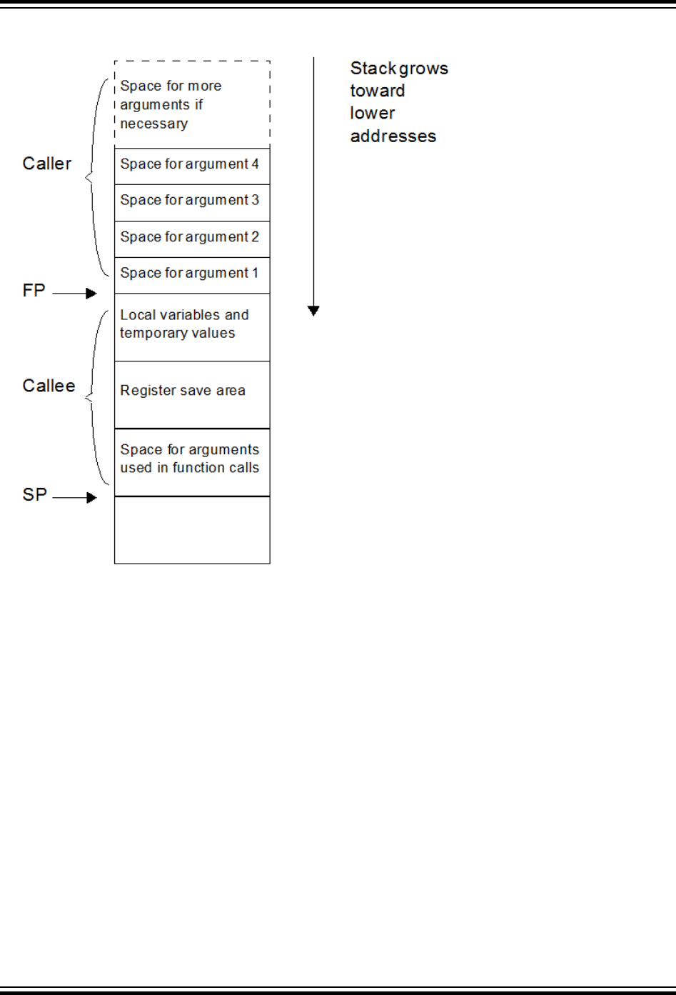
Figure 10-1. Stack Frame
The the standard qualifiers const and volatile may both be used with auto variables and these do not affect how they
are positioned in memory. This implies that a local const-qualified object is still an auto object and, as such, will be
allocated memory on the stack in the data memory, not in the program memory like with non-auto const objects.p
Local Variable Size Limits
There is no theoretical maximum size for auto variables.
10.4 Variables in Program Memory
The only variables that are placed into program memory are those that are not auto and which have been qualified
const. If the -mno-embedded-data option is used, then even const objects are placed in RAM rather than the
program memory. Any auto variables qualified const are placed on the stack along with other auto variables.
Note: For devices with internal Flash, a const-qualified variable combined with the default -membedded-data
option can be used to place a constant in nonvolatile Flash memory.
Any const-qualified (auto or non-auto) variable will always be read-only and any attempt to write to these in your
source code will result in an error being issued by the compiler.
XC32 Compiler for PIC32M
Memory Allocation and Access
© 2020 Microchip Technology Inc.
User Guide
DS50002799B-page 127

A const object is usually defined with initial values, as the program cannot write to these objects at runtime.
However this is not a requirement. An uninitialized const object is allocated space in the bss section, along with
other uninitialized RAM variables, but is still treated as read-only by the compiler.
const char IOtype = ’A’; // initialized const object
const char buffer[10]; // I just reserve memory in RAM
10.4.1 Size Limitations of const Variables
There is no theoretical maximum size for const variables.
10.4.2 Changing the Default Allocation
If you only intend to prevent all variables from using one or more program memory locations so that you can use
those locations for some other purpose, you are best reserving the memory using the memory adjust options.
If only a few non-auto const variables are to be located at specific addresses in program space memory, then the
variables should use the address attribute to locate them at the desired location. This attribute is described in 9.11
Variable Attributes .
10.5 Variable in Registers
Allocating variables to registers, rather than to a memory location, can make code more efficient. With MPLAB XC32
C/C++ Compiler, variables may be allocated to registers as part of code optimizations. For optimization levels 1 and
higher, the values assigned to variables may cached in a register. During this time, the memory location associated
with the variable may not hold a valid value.
The register keyword may be used to indicate your preference for the variable to be allocated a register, but this is
just a recommendation and may not be honored. The specific register may be indicated as well, but this is not
recommended as your register choice may conflict with the needs of the compiler. Using a specific register in your
code may cause the compiler to generate less efficient code.
As indicated in 14.6 Function Parameters, parameters may be passed to a function via a register.
Example 10-1. Variables in Registers
volatile unsigned int special;
unsigned int example (void)
{
register unsigned int my_reg __asm__("$4");
my_reg += special;
return my_reg;
}
10.6 Application-Defined Memory Regions
On occasion, an application may require a new memory region that was not defined in the default device-specific
linker scripts. One such case may be when using external memory connected to the External Bus Interface (EBI) on
a PIC32MZ target device.
One way to handle adding a new memory region would be to create a custom linker script, add the new memory
region, and explicitly map your sections to the new region. Another way to add a new memory region would be to add
an application-defined memory region to your C/C++ source code. Some applications may even choose to combine a
custom linker script and an application-defined memory region.
10.6.1 Advantages of an Application-Defined Memory Region
Using an application-defined memory region in source code can provide a few advantages over adding a memory
region to a custom linker script.
XC32 Compiler for PIC32M
Memory Allocation and Access
© 2020 Microchip Technology Inc.
User Guide
DS50002799B-page 128

• Portability: An application-defined memory region can help reduce the need for a custom linker script. This can
be beneficial because you can use the device's default linker script and thereby avoid potential migration issues
between XC32 versions, as well as between different PIC32 variants.
• Best-Fit Allocation: Region-attributed variables and functions are handled by the linker's best-fit allocator, as
described in the MPLAB XC32 Assembler, Linker, and Utilities User's Guide (DS50002186). Sections mapped to
a new region in a custom linker script must be explicitly mapped using the SECTIONS command and are
allocated sequentially.
10.6.2 Advantages of a Linker Script-Defined Memory Region
Using a custom linker script with a new memory region can also provide advantages over an application-defined
memory region.
• Update memory mapping at link time: A custom linker script allows you to easily switch between different
memory mappings without rebuilding your C/C++ code.
• Standard GNU Binutils: A user migrating from another toolchain based on GNU Binutils may already be familiar
and comfortable with creating new memory regions in a custom linker script. XC32 supports this standard
mechanism.
10.6.3 Using an Application-Defined Memory Region
To use this feature, work through the following sections.
Define a New Memory Space
The XC32 toolsuite requires information about each memory region. In order for the XC32 linker to be able to
properly assign memory, you must specify information about the size of the memory region available and the origin of
the memory region.
Define an application-defined memory region, with the origin and the size, using the 'region' pragma as shown
below.
#pragma region name=name origin=address size=bytes
where name is a quoted string containing the name of the region, address is the starting address of the region, and
bytes is the size in bytes of the region.
Example 10-2. Defining a New Memory Space
#pragma region name="ext_mem" origin=0xC0000000 size=0x1000
In this example, we define an application-defined memory region to be used for external memory. We name the
region "ext_mem" and specify that the starting address is 0xC0000000 and that it has a size of 0x1000 bytes.
Consult your PIC32 device data sheet for information about the external-memory interface options and the memory
mappings available on your device.
Define Variables within a Region
When you have defined a new memory region, you can then assign a variable to that region. Use the region attribute
on a variable to specify that it should be allocated to the specified region. This requires the memory region definition
to be present. Given the definition in the previous subsection, you can make the following variable definition:
int ext_array[256] __attribute__((region("ext_mem")));
ext_array will be allocated in the previously declared region "ext_mem".
Once the variable has been defined with the region attribute, it may be accessed using normal C syntax.
When called with the --report-mem linker command-line option, the linker prints a summary of memory usage to
stdout. When the application-defined memory region is used, the length of each section allocated to a region and the
total region memory used is displayed.
Define Functions within a Region
XC32 Compiler for PIC32M
Memory Allocation and Access
© 2020 Microchip Technology Inc.
User Guide
DS50002799B-page 129

You can also use the region attribute to assign individual functions to the region. This requires the memory region
definition to be present. Given the definition in the previous subsection, you can make the following function
definition:
int __attribute__((far, region("ext_mem"))) foo()
{
ext_array[2] = ext_array[0] + ext_array[1] ;
return 0;
}
Use the region attribute with the far attribute to allocate the function in our example "ext_mem" region. In this case,
we need the far attribute because the address of our "ext_mem" region is located outside of the 256 MB segment
of our default program-memory region, kseg0_program_mem, as defined in our default linker script. Using the far
attribute tells the compiler to generate a long call.
Initializing Memory Interfaces
When your application-defined memory region corresponds to an external-memory interface such as the Serial Quad
Interface (SQI) or External Bus Interface (EBI), you will likely need to configure the interface module. For instance,
the EBI module must be configured to understand such things as the type, size, and bus width of each attached
device. See the device data sheet and the family reference manual for your target device.
The default XC32 runtime start-up code uses a linker-generated data-initialization template placed in a section
named .dinit. (See 16.2.5 Initialize of Clear Variable and RAM Functions Using the Data-Initialization Template). For
variables or functions placed in an application-defined memory region, the application must execute any memory-
interface configuration code before the runtime start-up code attempts to initialize these variables or functions.
The default runtime start-up code provides an _on_reset() weak hook. This routine is called after initializing a
minimum ‘C’ context, but before data initialization. You can provide your memory-interface configuration code in this
hook. See 16.3 The On Reset Routine for more information on this important hook.
Example 10-3. Hardware Init Before Data Init
/* The _on_reset() function will be called by the default
runtime start-up code prior to data initialization. */
void _on_reset (void)
{
/* Call a function that configures the EBI control
registers for the target board. */
configure_ebi_sram();
}
On some target devices, your application may also need to enable the Memory Management Unit (MMU) and
initialize the Translation Lookaside Buffer (TLB). On many devices, the XC32 toolchain provides a default mapping
suitable for the SQI and EBI interfaces. See your target device data sheet for information on default memory mapping
that is specific to your target device. For devices where a default SQI and EBI mapping is provided, you can override
the default mapping by providing your own __pic32_tlb_init_ebi_sqi() function.
The source code for this is found in the pic32m-libs.zip file located at:
<install-directory>/pic32-libs/
Once the file is unzipped, the source code can be found at:
pic32m-libs/libpic32/stubs/pic32_init_tlb_ebi.S.
The following sections provide example cases using the application-defined memory region feature.
Example 10-4. Case 1
Variables can be placed in external memory by using the region attribute.
#pragma region name="ext_mem" origin=0x0xC0000000 size=0x1000
signed int ea1 __attribute__((region("ext_mem")));
unsigned int ea2 __attribute__((region("ext_mem")));
XC32 Compiler for PIC32M
Memory Allocation and Access
© 2020 Microchip Technology Inc.
User Guide
DS50002799B-page 130

signed int eb1[10] __attribute__((region("ext_mem"))) = {10,20};
signed long eb2[10] __attribute__((region("ext_mem"))) =
{0x987654321, 0x12345678};
Example 10-5. Case 2
Functions can be placed in external memory by using the region attribute. Since functions default
to space(prog), the function is assumed to be programmed into the region and will not be
initialized by the runtime start-up code.
#pragma region name="ext_flash" origin=0xC0000000 size=0x1000
int ea1 __attribute__((region("ext_flash"))) ;
int eb1 __attribute__((region("ext_flash"))) = 0x1000 ;
int ec1 __attribute__((region("ext_flash"))) = 0x2000 ;
void __attribute__((region("ext_flash"))) foo()
{
ea1 = eb1 + ec1 ;
}
void main()
{
foo();
}
Apply the far attribute to foo(), since it is out of range of the default kseg0_program_mem
region. Alternatively, use -mlong-calls option to compile the above example.
Example 10-6. Case 3
Combine the region attribute with the space(data) attribute to indicate that the function code should
be initialized by the runtime start-up code's data initialization template. In this case, the code for the
function is contained in the data-initialization template and copied to the memory region at startup.
#pragma region name="myebi_sram" origin=0xC0004000 size=0x100
void __attribute__((far,space(data),region("myebi_sram"))) fn_in_sram()
{ /* Code here */ }
Example 10-7. Case 4
Combine the region attribute with the address() attribute to place a variable at an absolute address
within the region.
#pragma region name="myebi_2" origin=0xC0001000 size=0x10
unsigned long __attribute__((region("myebi_2"),address(0xC0001000))) paws =
0xAAAABBBB;
10.7 Dynamic Memory Allocation
The run-time heap is an uninitialized area of data memory that is used for dynamic memory allocation using the
standard C library dynamic memory management functions, calloc, malloc and realloc along with the C++ new
operator. Most C++ applications will require a heap.
If you do not use any of these functions, then you do not need to allocate a heap. By default, a heap is not created.
In MPLAB X, you can specify a heap size in the project properties for the xc32-ld linker. MPLAB X will automatically
pass the option to the linker when building your project.
XC32 Compiler for PIC32M
Memory Allocation and Access
© 2020 Microchip Technology Inc.
User Guide
DS50002799B-page 131

If you do want to use dynamic memory allocation, either directly, by calling one of the memory allocation functions, or
indirectly, by using a standard C library function that uses one of these functions, then a heap must be created. A
heap is created by specifying its size on the linker command line using the --defsym,min_heap_size linker
command line option. An example of allocating a heap of 512 bytes using the command line is:
xc32-gcc foo.c -Wl,--defsym,min_heap_size=512
An example of allocating a heap of 0xF000 bytes using the xc32-g++ driver is:
xc32-g++ vector.cpp -Wl,--defsym,min_heap_size=0xF000
The linker allocates the heap immediately before the stack.
10.8 Memory Models
MPLAB XC32 C/C++ Compiler does not use fixed memory models to alter allocation of variables to memory.
The -G option (see 6.7.1 Options Specific to PIC32M Devices), which controls the gp-relative addressing threshold,
is similar to the small-data/large-data/scalar-data memory models offered by the Microchip compilers for the 8- and
16-bit architectures. The value specified with this option indicates the maximum size of objects that will be allocated
to the small data sections, for example, sbss, sdata, etc. Variables allocated to the small-data sections require
fewer instructions to access than variables allocated to the other data sections. For example:
xc32-gcc -G128 -mprocessor=32MX795F512L main.c
In this example, data objects up to 128 bytes in size will be located in the efficient small-data or small-bss section.
In general larger -G values result in more efficient code. However, gp-relative addressing is limited to 64-KB of small
data.
XC32 Compiler for PIC32M
Memory Allocation and Access
© 2020 Microchip Technology Inc.
User Guide
DS50002799B-page 132

11. Fixed-Point Arithmetic Support
The MPLAB XC32 C/C++ Compiler supports fixed-point arithmetic. This, according to the N1169 draft of ISO/IEC TR
18037, the ISO C99 technical report on Embedded C. It is available at: http://www.open-std.org/JTC1/SC22/
WG14/www/projects#18037.
This chapter describes the implementation-specific details of the types and operations supported by the compiler
under this draft standard.
Because of the sensitivity of DSP applications to performance, application developers have historically tended to
write functions in assembly. However, the XC32 compiler reduces, and may even eliminate, the need to write
assembly code. This chapter describes coding styles and usage tips that can help you to obtain the best
optimizations for your DSP application and to take advantage of the DSP-enhanced core that is available on many of
the PIC32 MCU families.
Several Microchip PIC32 MCUs feature a DSP-enhanced core with four 64-bit accumulators. The DSP-enhanced
core also provides a set of new instructions and a new architectural state, with computational support for fractional
data types, SIMD (Single Instruction, Multiple Data), saturation, and other operations commonly used in DSP
applications.
Note: Consult the data sheet for your specific target device to determine whether your target device supports the
DSP-enhanced core.
11.1 Enabling Fixed-Point Arithmetic Support
Fixed-point arithmetic support is enabled by default in the MPLAB XC32 C/C++ compiler. The compiler automatically
enables support for the DSP-enhanced core when you are compiling for an appropriate PIC32 target device as
selected by the -mprocessor option.
11.2 Data Types
All 12 of the primary fixed-point types and their aliases, described in Section 4.1 “Overview and principles of the
fixed-point data types” of the N1169 draft of ISO/IEC TR 18037, are supported. Fixed-point data values contain
fractional and optional integral parts. The format of fixed-point data in XC32 are as specified in the table below.
In the formats shown, “s” is the sign bit for a signed type (there is no sign bit for an unsigned type). The period
character “.” is the specifier that separates the integral part and the fractional part. The numeric digits represent the
number of bits in the integral part or in the fractional part.
Table 11-1. Fixed Point Formats
Type Format Description
short _Fract
s.7 (Q7) 1 bit sign, 7 bits fraction
unsigned short _Fract
0.8 8 bits fraction
_Fract
s.15 (Q15) 1 bit sign, 15 bits fraction
unsigned _Fract
0.16 16 bits fraction
long _Fract
s.31 (Q31) 1 bit sign, 31 bits fraction
unsigned long _Fract
0.32 32 bits fraction
long long _Fract
s.63 (Q63) 1 bit sign, 63 bits fraction
unsigned long long _Fract
0.64 64 bits fraction
short _Accum
s8.7 (Q8.7) 1 bit sign, 8 bits integer, 7 bits
fraction
unsigned short _Accum
8.8 8 bits integer, 8 bits fraction
XC32 Compiler for PIC32M
Fixed-Point Arithmetic Support
© 2020 Microchip Technology Inc.
User Guide
DS50002799B-page 133

...........continued
Type Format Description
_Accum
s16.15 (Q16.15) 1 bit sign, 16 bits integer, 15 bits
fraction
unsigned _Accum
16.16 16 bits integer, 16 bits fraction
long _Accum
s32.31 (Q32.31) 1 bit sign, 32 bits integer, 31 bits
fraction
unsigned long _Accum
32.32 32 bits integer, 32 bits fraction
long long _Accum
s32.31 (Q32.31) 1 bit sign, 32 bits integer, 31 bits
fraction
unsigned long long _Accum
32.32 32 bits integer, 32 bits fraction
The _Sat-type specifier, indicating that the values are saturated, may be used with any type as described in the
N1169 draft of ISO/IEC TR 18037. For example:
_Sat short _Fract; // s.7 (Q7)
_Sat _Fract; // s.15 (Q15)
_Sat long _Fract; // s.31 (Q31)
_Sat long long _Fract; // s.63 (Q63)
_Sat short _Accum; // s8.7 (Q8.7)
_Sat _Accum; // s16.15 (Q16.15)
_Sat long _Accum; // s32.31 (Q32.31)
_Sat long long _Accum; // s32.31 (Q32.31)
The representation of unsigned types differ from their corresponding signed types due to the fact that one bit is
utilized to store the sign. Signed types saturate at the most negative and positive numbers representable in the
corresponding format. Unsigned types saturate at zero and the most positive number representable in the format.
The default behavior of overflow on signed or unsigned types is saturation. The pragmas described in Section 4.1.3
"Rounding and Overflow" of the N1169 draft of ISO/IEC TR 18037 to control the rounding and overflow behavior are
not supported.
Use a suffix in a fixed-point literal constant:
• hr or HR for short _Fract and _Sat short _Fract
• r or R for _Fract and _Sat _Fract
• lr or LR for long _Fract and _Sat long _Fract
• llr or LLR for long long _Fract and _Sat long long _Fract
• uhr or UHR for unsigned short _Fract and _Sat unsigned short _Fract
• ur or UR for unsigned _Fract and _Sat unsigned _Fract
• ulr or ULR for unsigned long _Fract and _Sat unsigned long _Fract
• ullr or ULLR for unsigned long long _Fract and _Sat unsigned long long _Fract
• hk or HK for short _Accum and _Sat short _Accum
• k or K for _Accum and _Sat _Accum
• lk or LK for long _Accum and _Sat long _Accum
• llk or LLK for long long _Accum and _Sat long long _Accum
• uhk or UHK for unsigned short _Accum and _Sat unsigned short _Accum
• uk or UK for unsigned _Accum and _Sat unsigned _Accum
• ulk or ULK for unsigned long _Accum and _Sat unsigned long _Accum
XC32 Compiler for PIC32M
Fixed-Point Arithmetic Support
© 2020 Microchip Technology Inc.
User Guide
DS50002799B-page 134

• ullk or ULLK for unsigned long long _Accum and _Sat unsigned long long _Accum
11.3 External Definitions
The MPLAB XC32 C compiler provides an include file, stdfix.h, which defines various pre-processor macros related
to fixed-point support.
Fixed-point conversion specifiers for formatted I/O, as described in Section 4.1.9 "Formatted I/O functions for fixed-
point arguments" of the N1169 draft of ISO/IEC TR 18037, are not supported in the current MPLAB XC32 standard C
libraries. Fixed-point variables may be displayed via (s)printf by casting them to the appropriate floating-point
representation (float for _Fract, double for long _Fract and _Accum) and then displaying the value in that
format. To scan a fixed-point number via (s)scanf, first scan it as the appropriate float or double floating-point
number and then cast the value obtained to the desired fixed-point type.
The fixed-point functions described in Section 4.1.7 of N1169 are not provided in the current MPLAB XC32 standard
C libraries.
Fixed-point constants, with suffixes of k (K) and r (R), as described in Section 4.1.5 of N1169, are supported by the
MPLAB XC32 C compiler.
Usage example:
#include <stdfix.h>
void main () {
int i;
fract a[5] = {0.5,0.4,0.2,0.0,-0.1};
fract b[5] = {0.1,0.8,0.6,0.5,-0.1};
accum dp = 0;
/* Calculate dot product of a[] and b[] */
for (i=0; i<5; i++) {
dp += a[i] * b[i];
}
}
Integer representation of Q15 and Q31
The Q15 data type can be represented by the 16-bit integer data type (short) and the Q31 data type can be
represented by the 32-bit integer data type (int). These types are necessary when using the compiler's DSP built-in
functions (see 25. Built-In Functions). Typedefs are useful for Q15 and Q31 as follows:
typedef short q15;
typedef int q31;
The four 64-bit accumulators in the DSP-enhanced core can be represented by the "long long" data type.
typedef long long a64;
To initialize Q15 variables, multiply the fractional value (for example, 0.1234) by 0x1.0p15. To initialize Q31
variables, programmers can multiply the fractional value by 0x1.0p31.
Ex: /* Q15 Example */
typedef short q15;
q15 a = 0.1234 * 0x1.0p15;
/* ------------------------------------------------------ */
Ex: /* Q31 Example */
typedef int q31;
q31 b = 0.2468 * 0x1.0p31;
11.4 SIMD Variables
The 8-bit unsigned integer data and Q15 fractional data are packed in a single 32-bit register, and the new
instructions operate simultaneously on the multiple data in the register in Single Instruction, Multiple Data (SIMD)
fashion. This feature provides computation parallelism for increased application performance.
XC32 Compiler for PIC32M
Fixed-Point Arithmetic Support
© 2020 Microchip Technology Inc.
User Guide
DS50002799B-page 135

You can directly take advantage of SIMD parallelism by declaring SIMD data types as described here. In addition, the
compiler may automatically take advantage of SIMD parallelism using auto-vectorization as described in the Auto-
vectorization section below.
To declare SIMD data types, typedefs with special vector_size attributes are required. For example,
typedef signed char v4i8 __attribute__ ((vector_size(4)));
typedef signed char v4q7 __attribute__ ((vector_size(4)));
typedef short v2i16 __attribute__ ((vector_size(4)));
typedef short v2q15 __attribute__ ((vector_size(4)));
v4i8, v4q7, v2i16, and v2q15 are SIMD data types that consist of 4, 4, 2, and 2 elements of 8 bits, 8 bits, 16 bits,
and 16 bits respectively in a single variable/register.
SIMD data types are powerful and can be applied to fixed-point data types as well. For example:
typedef _Sat unsigned short _Fract
sat_v4uqq __attribute__ ((vector_size(4)));
typedef _Sat unsigned _Fract
sat_v2uhq __attribute__ ((vector_size(4)));
typedef _Sat unsigned short _Accum
sat_v2uha __attribute__ ((vector_size(4)));
typedef _Sat _Fract
sat_v2hq __attribute__ ((vector_size(4)));
typedef _Sat short _Accum
sat_v2ha __attribute__ ((vector_size(4)));
To initialize SIMD variables is similar to initializing aggregate data. The following examples show how to initialize
SIMD variables.
Example:
/* v4i8 Example */
v4i8 a = {1, 2, 3, 4};
v4i8 b;
b = (v4i8) {5, 6, 7, 8};
/* ------------------------------------------------------ */
Ex: /* v2q15 Example */
v2q15 a = {0x0fcb, 0x3a75};
v2q15 b;
b = (v2q15) {0.1234 * 32768.0, 0.4567 * 32768.0};
Data is stored from the right-to-left location of a register. For the example of v4i8 a = {1, 2, 3, 4}, the register stores 1,
2, 3, and 4 from the right-to-left location as shown below.
a[3]=4 a[2]=3 a[1]=2 a[0]=1
Bit 31 Bit 0
Most arithmetic operations will simply work on the SIMD operands in the register irrespective of their right-to-left
location within the register. However, you must be aware of such instructions that directly refer to the left or right
portions of a register. For example, MAQ_SA.W.PHL.
11.5 Accessing Elements in SIMD Variables
The use of SIMD variables enables operations on multiple data in parallel. However, in certain situations,
programmers need to access elements inside a SIMD variable. This can be done by using a union type that unites a
SIMD type and an array of a basic type as follows.
typedef union
{
v4i8 a;
unsigned char b[4];
} v4i8_union;
typedef short q15;
typedef union
XC32 Compiler for PIC32M
Fixed-Point Arithmetic Support
© 2020 Microchip Technology Inc.
User Guide
DS50002799B-page 136

{
v2q15 a;
q15 b[2];
} v2q15_union;
As shown in the figure above for a v4i8 variable, b[0] is used to access the first element in the variable. The
element b[0] is right-most position. The following examples show how to extract or assign elements.
Example:
/* v4i8 Example */
v4i8 i;
unsigned char j, k, l, m;
v4i8_union temp;
/* Assume we want to extract from i. */
temp.a = i;
j = temp.b[0];
k = temp.b[1];
l = temp.b[2];
m = temp.b[3];
/* Assume we want to assign j, k, l, m to i. */
temp.b[0] = j;
temp.b[1] = k;
temp.b[2] = l;
temp.b[3] = m;
i = temp.a;
/* -------------------------------------------------------- */
Example:
/* v2q15 Example */
v2q15 i;
q15 j, k;
v2q15_union temp;
/* Assume we want to extract from i. */
temp.a = i;
j = temp.b[0];
k = temp.b[1];
/* Assume we want to assign j, k to i. */
temp.b[0] = j;
temp.b[1] = k;
i = temp.a;
Using SIMD data types is a very powerful technique. Programmers can enjoy the performance improvement from
SIMD data types by calling the DSP built-in functions (see 25. Built-In Functions) and/or using generic C operators.
For SIMD data types, the compiler can map C operators (e.g., +, -, *, /) to hardware instructions directly, so long as
the selected target PIC32 MCU features the DSP-enhanced core.
Note: In many cases, optimization level -O1 or greater may be required to optimize the code to use the SIMD
instruction.
Here are some examples:
typedef signed char v4i8 __attribute__ ((vector_size(4)));
v4i8 a, b, c;
c = a + b; // compiler generates addu.qb
c = a - b; // compiler generates subu.qb
/* -------------------------------------------------------- */
typedef short v2q15 __attribute__ ((vector_size(4)));
v2q15 d, e, f;
f = d + e; // compiler generates addq.ph
f = d - e; // compiler generates subq.ph
/* -------------------------------------------------------- */
typedef short v2i16 __attribute__ ((vector_size(4)));
v2i16 x, y, z;
z = x * y; // compiler generates mul.ph
/* -------------------------------------------------------- */
typedef _Sat _Fract sat_v2hq __attribute__ ((vector_size(4)));
sat_v2hq a, b, c;
c = a + b; // compiler generates addq_s.ph
XC32 Compiler for PIC32M
Fixed-Point Arithmetic Support
© 2020 Microchip Technology Inc.
User Guide
DS50002799B-page 137

c = a - b; // compiler generates subq_s.ph
c = a * b; // compiler generates mulq_rs.ph
Note: When char or short data elements are packed into SIMD data types, the first data must be aligned to 32 bits;
otherwise, the unaligned memory accesses may generate general exceptions or decrease performance.
11.6 Array Alignment and Data Layout
The compiler provides a mechanism to specify the alignment of variables by using __attribute__ ((aligned
(bytes))). The alignment is important to loading or storing SIMD variables: "v4i8" and "v2q15". If an array is
aligned to a 4-byte boundary, that is, word-aligned, the compiler can load or store four 8-bit data for v4i8 variables
(or two 16-bit data for v2q15 variables) at a time using the load word class of instructions. The following example
shows that when a char array A is aligned to a 4-byte boundary, we can cast this array to a v4i8 array and load four
items to a v4i8 variable at a time by using the lwx instruction. However, if this char array A is not aligned to a 4-byte
boundary, executing the following code will result in an address exception due to a mis-aligned load.
Example:
/* v4i8 Example */
char A[128] __attribute__ ((aligned (4)));
v4i8 test (int i)
{
v4i8 a;
v4i8 *myA = (v4i8 *)A;
a = myA[i];
return a;
}
# Illustrative generated assembly with optimizations
test:
lui $2,%hi(A)
sll $4,$4,2
addiu $2,$2,%lo(A)
lwx $2,$2($4)
j $31
After SIMD data is loaded from memory into a register, ensure that the SIMD variables in the register are ready for
use without requiring any rearrangement of the data. To avoid such data rearrangement which can reduce the benefit
of parallelism, design your array with an efficient data layout that is favorable for SIMD calculations.
11.7 C Operators
11.7.1 Operations on Fixed-Point Variables
Support for fixed-point types includes:
• prefix and postfix increment and decrement operators (++, --)
• unary arithmetic operators (+, -, !)
• binary arithmetic operators (+, -, *, /)
• binary shift operators (<<, >>)
• relational operators (<, <=, >=, >)
• equality operators (==, !=)
• assignment operators (+=, -=, *=, /=, <<=, >>=)
• conversions to and from integer, floating-point, or fixed-point types
This is an example of a multiplication operator.
Example:
#include <stdfix.h>
sat fract test (sat fract a, sat fract b)
{
return (a * b);
XC32 Compiler for PIC32M
Fixed-Point Arithmetic Support
© 2020 Microchip Technology Inc.
User Guide
DS50002799B-page 138

}
# Illustrative generated assembly with optimizations
test:
mulq_rs.ph $2,$4,$5
j $31
11.8 Operations on SIMD Variables
Some specific C operators can be applied to SIMD variables. They are +, -, *, /, unary minus, ^, |, &, ~. The DSP-
enhanced core provides SIMD addition and subtraction instructions for v4i8 and v2q15, allowing the XC32 to
generate appropriate instructions for addition and subtraction of v4i8 and v2q15 variables. For other operators, the
compiler synthesizes a sequence of instructions. The examples here show compiler-generated SIMD instructions
when the appropriate operator is applied to SIMD variables.
Example:
/* v4i8 Addition */
v4i8 test (v4i8 a, v4i8 b)
{
return a + b;
}
# Illustrative generated assembly with optimizations
test:
addu.qb $2, $4, $5
j $31
# ----------------------------------------------------------
Example:
/* v4i8 Subtraction */
v4i8 test (v4i8 a, v4i8 b)
{
return a - b;
}
# Illustrative generated assembly with optimizations
test:
subu.qb $2, $4, $5
j $31
# ----------------------------------------------------------
Example:
/* v2q15 Addition */
v2q15 test (v2q15 a, v2q15 b)
{
return a + b;
}
# Illustrative generated assembly with optimizations
test:
addq.ph $2, $4, $5
j $31
# ----------------------------------------------------------
Example:
/* v2q15 Subtraction */
v2q15 test (v2q15 a, v2q15 b)
{
return a - b;
}
# Illustrative generated assembly with optimizations
test:
subq.ph $2, $4, $5
j $31
In situations where your application requires special integer and fractional calculations and the compiler cannot
generate them automatically, you can use the DSP built-in functions (see 25. Built-In Functions).
XC32 Compiler for PIC32M
Fixed-Point Arithmetic Support
© 2020 Microchip Technology Inc.
User Guide
DS50002799B-page 139

11.9 DSP Built-In Functions
Built-in functions are very similar to standard function calls in syntax. Your application passes parameters to a built-in
function, and the built-in function returns the result to variables. The difference between a built-in function and a
standard function is that the compiler directly can map the built-in function to a specific instruction sequence for better
performance. The DSP built-in functions are listed in (see 25. Built-In Functions).
11.10 DSP Control Register
The DSP-enhanced core includes a DSP control register that has six fields: CCOND (condition code bits), OUFLAG
(overflow/underflow bits), EFI (extract fail indicator bit), C (carry bit), SCOUNT (size count bits) and POS (position
bits). The compiler treats the SCOUNT and POS fields as global variables, such that instructions that modify
SCOUNT or POS are never optimized away. These instructions include WRDSP, EXTPDP, EXTPDPV, and MTHLIP.
A function call that jumps to a function containing WRDSP, EXTPDP, EXTPDPV, or MTHLIP is also never deleted by
the compiler.
For correctness, you must assume that a function call clobbers all fields of the DSP control register. That is, do not
depend on the values in CCOND, OUFLAG, EFI or C across a function-call boundary. Re-initialize the values of
CCOND, OUFLAG, EFI or C before using them. Note that because SCOUNT and POS fields are treated as global
variables, the values of SCOUNT and POS are always valid across function-call boundaries and can be used without
re-initialization.
The following example shows possibly incorrect code. The first built-in function "__builtin_mips_addsc" sets the
carry bit (C) in the DSP control register, and the second built-in function "__builtin_mips_addwc" reads the carry
bit (C) from the DSP control register. However, a function call "func" inserted between "__builtin_mips_addsc"
and "__builtin_mips_addwc" may change the carry bit to affect the correct result of "__builtin_mips_addwc".
Incorrect Ex:
int test (int a, int b, int c, int d)
{
__builtin_mips_addsc (a, b);
func(); // may clobber the carry bit
return __builtin_mips_addwc (c, d);
}
The previous example may be corrected by moving "func" before the first built-in function or after the second built-in
function as follows. p
Corrected Ex:
int test (int a, int b, int c, int d)
{
func(); // may affect the carry bit
__builtin_mips_addsc (a, b);
return __builtin_mips_addwc (c, d);
}
/* -------------------------------------------------------- */
int test (int a, int b, int c, int d)
{
int i;
__builtin_mips_addsc (a, b);
i = __builtin_mips_addwc (c, d);
func(); // may affect the carry bit
return i;
}
11.11 Using Accumulators
To access only HI or LO of an accumulator, use a union type as follows.
typedef union
{
long long a; // One 64-bit accumulator
XC32 Compiler for PIC32M
Fixed-Point Arithmetic Support
© 2020 Microchip Technology Inc.
User Guide
DS50002799B-page 140

int b[2]; // 32-bit HI and LO
} a64_union;
To access HI, use b[1]. To access LO, use b[0].
Example:
int test (long long a, v2q15 b, v2q15 c)
{
a64_union temp;
temp.a = __builtin_mips_dpaq_s_w_ph (a, b, c);
return temp.b[0]; // access LO.
}
11.12 Mixed-Mode Operations
11.12.1 Multiply "32-bit int * 32-bit int = 64-bit long long int"
Multiply "32-bit int * 32-bit int = 64-bit long long int"
To multiply 32 bits by 32 bits to obtain a 64-bit result, cast the 32-bit integer to a 64-bit integer (long long) and then
perform the multiplication operation as follows.
Example:
long long test (int a, int b)
{
return (long long) a * b;
// Same as (long long) a * (long long) b
// NOT the same as (long long) (a * b)
}
We can then access the highest 32-bit result from HI as follows.
Example:
typedef union
{
long long a; // One 64-bit accumulator
int b[2]; // 32-bit HI and LO
} a64_union;
int test (int a, int b)
{
a64_union temp;
temp.a = (long long) a * b;
return temp.b[1]; // Access the HI 32 bits
}
# Illustrative generated assembly with optimizations
test:
mult $4,$5
mfhi $2
j $31
11.12.2 Multiply and Add "32-bit int * 32-bit int + 64-bit long long = 64-bit long long int"
To perform multiplication and addition, cast the 32-bit integer to 64-bit (long long) and then perform multiplication and
addition as follows.
Example:
long long test (int a, int b, long long c)
{
return c + (long long) a * b;
}
# Illustrative generated assembly with optimizations
test:
mtlo $6
mthi $7
madd $4, $5
XC32 Compiler for PIC32M
Fixed-Point Arithmetic Support
© 2020 Microchip Technology Inc.
User Guide
DS50002799B-page 141

mflo $2
mfhi $3
j $31
11.13 Auto-Vectorization to SIMD
The compiler supports auto-vectorization for loops at optimization level -O3. The advantage of auto-vectorization is
that the compiler can recognize scalar variables (which can be integer, fixed-point, or floating-point types) in order to
utilize SIMD (Single Instruction, Multiple Data) instructions automatically. In the ideal case, when auto-vectorization is
used, there is no need to use SIMD variables explicitly.
Example:
/* add8.c */
unsigned char a[32], b[32], c[32];
void add8() {
int i;
for (i = 0; i < 32; i++)
{
c[i] = a[i] + b[i];
}
}
# Illustrative generated assembly code
add8:
lui v0,0x0
addiu v0,v0,0
lui a0,0x0
addiu a0,a0,0
lui v1,0x0
addiu v1,v1,0
addiu a3,v0,32
lw a2,0(a0)
lw a1,0(v0)
addiu v0,v0,4
addiu a0,a0,4
addu.qb a1,a2,a1
addiu v1,v1,4
bne v0,a3,1c <add8+0x1c>
sw a1,-4(v1)
jr ra
In add8.c, elements in two arrays of unsigned char are added together. The compiler automatically generates
the code for addu.qb to add four elements at a time.
For existing C code, try auto-vectorization at the -O3 optimization level without any modifications to see if the
compiler can auto vectorize the loops. In some cases, if the loop body is too complex, the compiler will not be able to
auto-vectorize the loop; in this case, you may choose to restructure and simplify the loop.
11.14 FIR Filter Example Project
The DSP_Intrinsics example project shows the advantages of a FIR filter implementation based on DSP Built-in
Functions compared to traditional C code, without any DSP optimizations. First, the filter is implemented for Q15
input data represented as arrays of short variables:
short coeff[BUFSIZE] __attribute__ ((aligned(4)));
short delay[BUFSIZE] __attribute__ ((aligned(4)));
The traditional C code version for Q15 inputs doesn't use SIMD variables or DSP Built-in Functions. Instead, it
implements the Q15 x Q15 multiplication by checking the saturation condition (both operands are 0x8000 or -1) and
then left shifting the integer multiplication result by 1 bit before adding it to the accumulator.
long long FIR_Filter_Traditional_16(short *delay, short *coeff, int buflen)
{
int i;
short x, y;
XC32 Compiler for PIC32M
Fixed-Point Arithmetic Support
© 2020 Microchip Technology Inc.
User Guide
DS50002799B-page 142

// 64-bit accumulator for result
long long ac0 = 0;
for (i = 0; i < buflen; i++) {
x = coeff[i];
y = delay[i];
// check saturation condition
if ((unsigned short)x == 0x8000 && (unsigned short)y == 0x8000) {
ac0 += 0x7fffffff;
} else {
// multiply (Q15 x Q15) needs left shift
// result is added to accumulator variable
ac0 += ((x * y) << 1);
}
}
return ac0;
}
For this C implementation the compiler generates inefficient assembly code. It does not have enough information to
auto-vectorize the loop.
# Illustrative generated assembly code
FIR_Filter_Traditional_16:
…
mul $24,$13,$15
sll $25,$24,1
addu $12,$2,$25
sra $9,$25,31
sltu $11,$12,$2
addu $3,$3,$9
move $2,$12
addu $3,$11,$3
In the DSP Intrinsics approach of the filter the input buffers are casted to the v2q15 SIMD vector type defined above
in section SIMD Variables. Inside the loop, the "__builtin_mips_dpaq_s_w_ph" DSP built-in function is called.
The result of the call is stored in the accumulator variable, of type Q32.31 (64-bit), represented as integer type a64
(see definition in section Integer representation of Q15 and Q31).
a64 FIR_Filter_Intrinsics_16(short *delay, short *coeff, int buflen)
{
int i;
v2q15 *my_delay = (v2q15 *)delay;
v2q15 *my_coeffs = (v2q15 *)coeff;
// 64-bit accumulator for result
a64 ac0 = 0;
for (i = 0; i < buflen/2; i++) {
ac0 = __builtin_mips_dpaq_s_w_ph (ac0,
my_delay[i],
my_coeffs[i]);
}
return ac0;
}
This function generates "dpaq_s.w.ph" assembly DSP instructions that apply the "Dot Product with Accumulate"
operation on two sets of Q15 values. The result is stored in one of the four 64-bit accumulators in the DSP-enhanced
core.
# Illustrative generated assembly code
FIR_Filter_Intrinsics_16:
…
mtlo $0
mthi $0
addiu $8,$7,-1
li $6,1
andi $10,$8,0x7
dpaq_s.w.ph $ac0,$2,$3
addiu $3,$4,4
beq $6,$7,.L60
addiu $2,$5,4
XC32 Compiler for PIC32M
Fixed-Point Arithmetic Support
© 2020 Microchip Technology Inc.
User Guide
DS50002799B-page 143

The project targets the PIC32MZ2048EFM144 device. The tools used are MPLAB X IDE v3.10, MPLAB XC32 v1.40
compiler and PIC32 MZ EF Starter Kit/Simulator. Optimization level is set at "-O3" with "-funroll-loops" option
enabled. Using an internal timer to count the ticks during calls to the 2 functions operating on the same Q15 data
buffers reveals that the Intrinsics version is approximately 4.52 times faster than the traditional C version.
Example timing output for input data buffers of size 2048:
16-bit without DSP Intrinsics: timer ticks 1180
16-bit with DSP Intrinsics: timer ticks: 261
The project includes filter implementations for buffers of 32-bit integer data types using similar approaches as for the
previous 16-bit versions.
First implementation uses multiply and add operators. The 32-bit is casted to 64-bit before multiply as it was
described previously in 11.12.2 Multiply and Add "32-bit int * 32-bit int + 64-bit long long = 64-bit long long int":
for (i = 0; i < buflen; i++) {
acc += (long long)data[i] * coeff[i];
}
# Illustrative generated assembly code
FIR_Filter_32:
…
lwx $24,$2($4)
lwx $25,$2($5)
addiu $2,$2,4
madd $ac0,$24,$25
The Intrinsics variant uses the "__builtin_mips_madd" to operate the multiply add.
for (i = 0; i < buflen; i++) {
acc = __builtin_mips_madd (acc, data[i], coeff[i]);
}
# Illustrative generated assembly code
FIR_Filter_Intrinsics_32:
…
lw $17,0($3)
lw $24,0($2)
addiu $7,$7,1
addiu $3,$3,4
addiu $2,$2,4
madd $ac0,$17,$24
The tick counts for the 32-bit implementations are very similar. In both cases the compiler is now generating the
"MADD" DSP instructions.
Example timing output for input data buffers of size 2048:
32-bit without DSP Intrinsics: timer ticks 520
32-bit with DSP Intrinsics: timer ticks 484
XC32 Compiler for PIC32M
Fixed-Point Arithmetic Support
© 2020 Microchip Technology Inc.
User Guide
DS50002799B-page 144

12. Operators and Statements
The MPLAB XC32 C/C++ Compiler supports all ANSI operators. The exact results of some of these are
implementation-defined. Implementation-defined behavior is fully documented in 23. Implementation-Defined
Behavior. The following sections illustrate code operations that are often misunderstood, as well as additional
operations that the compiler is capable of performing.
12.1 Integral Promotion
When there is more than one operand to an operator, they typically must be of exactly the same type. The compiler
will automatically convert the operands, if necessary, so they do have the same type. The conversion is to a “larger”
type so there is no loss of information; however, the change in type can cause different code behavior to what is
sometimes expected. These form the standard type conversions.
Prior to these type conversions, some operands are unconditionally converted to a larger type, even if both operands
to an operator have the same type. This conversion is called integral promotion and is part of Standard C behavior.
The MPLAB XC32 C/C++ Compiler performs these integral promotions where required, and there are no options that
can control or disable this operation. If you are not aware that the type has changed, the results of some expressions
are not what would normally be expected.
Integral promotion is the implicit conversion of enumerated types, signed or unsigned varieties of char, short
int or bit field types to either signed int or unsigned int. If the result of the conversion can be represented by
an signed int, then that is the destination type, otherwise the conversion is to unsigned int.
Consider the following example:
unsigned char count, a=0, b=50;
if(a - b < 10)
count++;
The unsigned char result of a - b is 206 (which is not less than 10), but both a and b are converted to signed
int via integral promotion before the subtraction takes place. The result of the subtraction with these data types is
-50 (which is less than 10) and hence the body of the if() statement is executed.
If the result of the subtraction is to be an unsigned quantity, then apply a cast. For example:
if((unsigned int)(a - b) < 10)
count++;
The comparison is then done using unsigned int, in this case, and the body of the if() would not be executed.
Another problem that frequently occurs is with the bitwise compliment operator, ~. This operator toggles each bit
within a value. Consider the following code:
unsigned char count, c;
c = 0x55;
if( ~c == 0xAA)
count++;
If c contains the value 0x55, it often assumed that ~c will produce 0xAA, however the result is 0xFFFFFFAA and so
the comparison in the above example would fail. The compiler may be able to issue a mismatched comparison error
to this effect in some circumstances. Again, a cast could be used to change this behavior.
The consequence of integral promotion as illustrated above is that operations are not performed with char -type
operands, but with int -type operands. However there are circumstances when the result of an operation is identical
regardless of whether the operands are of type char or int. In these cases, the MPLAB XC32 C/C++ Compiler will
not perform the integral promotion so as to increase the code efficiency. Consider the following example:
unsigned char a, b, c;
a = b + c;
XC32 Compiler for PIC32M
Operators and Statements
© 2020 Microchip Technology Inc.
User Guide
DS50002799B-page 145

Strictly speaking, this statement requires that the values of b and c should be promoted to unsigned int, the
addition performed, the result of the addition cast to the type of a, and then the assignment can take place. Even if
the result of the unsigned int addition of the promoted values of b and c was different to the result of the
unsigned char addition of these values without promotion, after the unsigned int result was converted back to
unsigned char, the final result would be the same. If an 8-bit addition is more efficient than a 32-bit addition, the
compiler will encode the former.
If, in the above example, the type of a was unsigned int, then integral promotion would have to be performed to
comply with the ANSI C standard.
12.2 Type References
Another way to refer to the type of an expression is with the typeof keyword. This is a non-standard extension to
the language. Using this feature reduces your code portability.
The syntax for using this keyword looks like sizeof, but the construct acts semantically like a type name defined
with typedef.
There are two ways of writing the argument to typeof: with an expression or with a type. Here is an example with an
expression:
typeof (x[0](1))
This assumes that x is an array of functions; the type described is that of the values of the functions.
Here is an example with a typename as the argument:
typeof (int *)
Here the type described is a pointer to int.
If you are writing a header file that must work when included in ANSI C programs, write _ _typeof_ _ instead of
typeof.
A typeof construct can be used anywhere a typedef name could be used. For example, you can use it in a
declaration, in a cast, or inside of sizeof or typeof.
• This declares y with the type of what x points to:
typeof (*x) y;
• This declares y as an array of such values:
typeof (*x) y[4];
• This declares y as an array of pointers to characters:
typeof (typeof (char *)[4]) y;
It is equivalent to the following traditional C declaration:
char *y[4];
To see the meaning of the declaration using typeof, and why it might be a useful way to write, let’s rewrite it with
these macros:
#define pointer(T) typeof(T *)
#define array(T, N) typeof(T [N])
Now the declaration can be rewritten this way:
array (pointer (char), 4) y;
Thus, array (pointer (char), 4) is the type of arrays of four pointers to char.
12.3 Labels as Values
You can get the address of a label defined in the current function (or a containing function) with the unary operator
'&&'. This is a non-standard extension to the language. Using this feature reduces your code portability.
XC32 Compiler for PIC32M
Operators and Statements
© 2020 Microchip Technology Inc.
User Guide
DS50002799B-page 146

The value returned has type void *. This value is a constant and can be used wherever a constant of that type is
valid. For example:
void *ptr;
...
ptr = &&foo;
To use these values, you need to be able to jump to one. This is done with the computed goto statement, goto
*exp;. For example:
goto *ptr;
Any expression of type void * is allowed.
One way of using these constants is in initializing a static array that will serve as a jump table:
static void *array[] = { &&foo, &&bar, &&hack };
Then you can select a label with indexing, like this:
goto *array[i];
Note: This does not check whether the subscript is in bounds. (Array indexing in C never does.)
Such an array of label values serves a purpose much like that of the switch statement. The switch statement is
cleaner and therefore preferable to an array.
Another use of label values is in an interpreter for threaded code. The labels within the interpreter function can be
stored in the threaded code for fast dispatching.
This mechanism can be misused to jump to code in a different function. The compiler cannot prevent this from
happening, so care must be taken to ensure that target addresses are valid for the current function.
12.4 Conditional Operator Operands
The middle operand in a conditional expression may be omitted. Then if the first operand is nonzero, its value is the
value of the conditional expression. This is a non-standard extension to the language. Using this feature reduces your
code portability.
Therefore, the expression:
x ? : y
has the value of x if that is nonzero; otherwise, the value of y.
This example is perfectly equivalent to:
x ? x : y
In this simple case, the ability to omit the middle operand is not especially useful. When it becomes useful is when
the first operand does, or may (if it is a macro argument), contain a side effect. Then repeating the operand in the
middle would perform the side effect twice. Omitting the middle operand uses the value already computed without the
undesirable effects of recomputing it.
12.5 Case Ranges
You can specify a range of consecutive values in a single case label, like this:
case low ... high:
This has the same effect as the proper number of individual case labels, one for each integer value from low to
high, inclusive. This is a non-standard extension to the language. Using this feature reduces your code portability.
This feature is especially useful for ranges of ASCII character codes:
case 'A' ... 'Z':
XC32 Compiler for PIC32M
Operators and Statements
© 2020 Microchip Technology Inc.
User Guide
DS50002799B-page 147

Be careful: Write spaces around the..., otherwise it may be parsed incorrectly when you use it with integer values. For
example, write this:
case 1 ... 5:
rather than this:
case 1...5:
XC32 Compiler for PIC32M
Operators and Statements
© 2020 Microchip Technology Inc.
User Guide
DS50002799B-page 148
13. Register Usage
This chapter examines registers used by the compiler to generate assembly from C/C++ source code.
13.1 Register Usage
The assembly generated from C/C++ source code by the compiler will use certain registers that are present on the
PIC MCU device. The compiler assumes that nothing other than code it generates can alter the contents of these
registers, but an extended assembly language format can be used to indicate to the compiler registers used in
assembly code so that code can be adjusted accordingly.
13.2 Register Conventions
The 32 general purpose registers contained in the PIC32 are shown in the table below. Some of these registers are
assigned a dedicated task by the compiler. The name used in assembly code and the usage is indicated.
Table 13-1. Register Conventions
Register Number Software Name Use
$0
zero
Always 0 when read.
$1
at
Assembler temporary variable. Do
not use the $at register from source
code unless you fully understand the
implications.
$2-$3
v0-v1
Return value from functions.
$4-$7
a0-a3
Used for passing arguments to
functions.
$8-$15
t0-t7
Temporary registers used by
compiler for expression evaluation.
Values not saved across function
calls.
$16-$23
s0-s7
Temporary registers whose values
are saved across function calls.
$24-$25
t8-t9
Temporary registers used by
compiler for expression evaluation.
Values not saved across function
calls.
$26-$27
k0-k1
Reserved for interrupt/trap handler.
$28
gp
Global Pointer.
$29
sp
Stack Pointer.
$30 fp or s8 Frame Pointer if needed. Additional
temporary saved register if not.
$31
ra
Return address for functions.
The PIC32MZ family uses the microMIPS compressed instruction-set architecture. You can use the micromips
function attribute to compile the function for the microMIPS compressed mode. This compressed ISA generally
results in a ~30% reduction in overall application code size at the expense of ~2% in performance. The
microcontroller can switch between the MIPS32 and microMIPS modes on a function call. Consult your device data
sheet to determine if your target device supports the microMIPS ISA.
XC32 Compiler for PIC32M
Register Usage
© 2020 Microchip Technology Inc.
User Guide
DS50002799B-page 149

Example function:
#include <xc.h>
void
__attribute__((micromips))
peanut (void)
{
// function code here
}
Important: Standard function calls can switch between MIPS32 and microMIPS modes. However, when
calling a MIPS32 library function from a microMIPS function, the compiler may generate a compressed
jals instruction to call the library function. A jals instruction cannot change modes to MIPS32 and upon
linking, you may receive an error, “Unsupported jump between ISA modes; consider recompiling with
interlinking enabled.” In that case, add the -mno-jals option to the Alternative Options field in your
project properties for xc32-gcc, so it is passed to the compiler.
XC32 Compiler for PIC32M
Register Usage
© 2020 Microchip Technology Inc.
User Guide
DS50002799B-page 150

14. Functions
The following sections describe how function definitions are written, and specifically how they can be customized to
suit your application. The conventions used for parameters and return values, as well as the assembly call
sequences are also discussed.
14.1 Writing Functions
Functions may be written in the usual way in accordance with the C/C++ language.
The only specifier that has any effect on function is static. Interrupt functions are defined with the use of the
interrupt attribute, see 14.2 Function Attributes and Specifiers.
A function defined using the static specifier only affects the scope of the function, that is, limits the places in the
source code where the function may be called. Functions that are static may only be directly called from code in
the file in which the function is defined. The equivalent symbol used in assembly code to represent the function may
change if the function is static, see 10.2.2 Static Variables. This specifier does not change the way the function is
encoded.
14.2 Function Attributes and Specifiers
14.2.1 Function Attributes
address(addr)
The address attribute specifies an absolute virtual address for the function. Be sure to specify the address attribute
using an appropriate virtual address for the target device. The address is typically in the range
[0x9D000000,0x9D0FFFFC], as defined in the linker script as the ‘kseg0_program_mem’ memory region. For
example,
__attribute__((address(0x9D008000))) void bar (void);
The compiler performs no error checking on the address. The section containing the function will be located at the
specified address regardless of the memory-regions specified in the linker script or the actual memory ranges on the
target device. The application code must ensure that the address is valid for the target device.
To make effective use of absolute sections and the new best-fit allocator, standard program-memory and data-
memory sections should not be mapped in the linker script. The built-in linker script does not map most standard
sections such as the .text, .data, .bss, or .ramfunc sections. By not mapping these sections in the linker script,
we allow these sections to be allocated using the best-fit allocator rather than the sequential allocator. Sections that
are unmapped in the linker script can flow around absolute sections, whereas sections that are linker-script mapped
are grouped together and allocated sequentially, potentially causing conflicts with absolute sections.
alias ("symbol")
Indicates that the function is an alias for another symbol. For example:
void foo (void) { /* stuff */ }
__attribute__ ((alias("foo"))) void bar (void);
Symbol bar is considered to be an alias for the symbol foo.
always_inline
If the function is declared inline, always inline the function, even if no optimization level was specified.
at_vector
Place the body of the function at the indicated exception vector address.
See 15. Interrupts and 15.4 Exception Handlers.
const
XC32 Compiler for PIC32M
Functions
© 2020 Microchip Technology Inc.
User Guide
DS50002799B-page 151

If a pure function determines its return value exclusively from its parameters (that is, does not examine any global
variables), it may be declared const, allowing for even more aggressive optimization. Note that a function which de-
references a pointer argument is not const since the pointer de-reference uses a value which is not a parameter,
even though the pointer itself is a parameter.
deprecated
deprecated (msg)
When a function specified as deprecated is used, a warning is generated. The optional msg argument, which must
be a string, will be printed in the warning if present. The deprecated attribute may also be used for variables and
types.
far
Always invoke the function by first loading its address into a register and then using the contents of that register. This
allows calling a function located beyond the 28-bit addressing range of the direct CALL instruction.
format (type, format_index, first_to_check)
The format attribute indicates that the function takes a printf, scanf, strftime, or strfmon style format string
and arguments and that the compiler should type check those arguments against the format string, just as it does for
the standard library functions.
The type parameter is one of printf, scanf, strftime or strfmon (optionally with surrounding double
underscores, for example, __printf__) and determines how the format string will be interpreted.
The format_index parameter specifies which function parameter is the format string. Function parameters are
numbered from the left-most parameter, starting from 1.
The first_to_check parameter specifies which parameter is the first to check against the format string. If
first_to_check is zero, type checking is not performed and the compiler only checks the format string for
consistency (for example, vfprintf).
format_arg (index)
The format_arg attribute specifies that a function manipulates a printf style format string and that the compiler
should check the format string for consistency. The function attribute which is a format string is identified by index.
function_replacement_prologue
This feature allows the application to redirect one function to another implementation at runtime without replacing the
existing function. This is achieved by changing the method of invoking functions through a function replacement table
instead of from a linker-resolved address. Initially the function address in the table points to the location of the entry
point of the original function's prologue. The application can then replace the table entry with the new function
address. Now, during the program execution, the control will pass to the new function address and returns to the
caller function. This feature adds a new function_replacement_prologue function attribute. To redirect the
function, modify the corresponding Function Replacement Table entry at runtime.
Example C code:
int a, b, c, d;
int __attribute__((function_replacement_prologue)) foo (void)
{
a = b + c;
return (a);
}
int main()
{
d = foo();
return 0;
}
Example generated assembly code:
# Function Replacement Table entries, located in data memory
.section .fixtable, data
fixtable.foo:
XC32 Compiler for PIC32M
Functions
© 2020 Microchip Technology Inc.
User Guide
DS50002799B-page 152

.word cont.foo # By default, populate the table with the address
# of the original implementation. Redirect to
# another implementation by overwriting this
# location with the address of the new implementation.
.section .text, code
.globl foo
.ent foo
.type foo, @function
foo:
# Begin Function Replacement Table Prologue
lui $25,%hi(fixtable.foo) # Load address from .fixtable above
lw $25,%lo(fixtable.foo)($25)
j $25 # Jump to address loaded from table
nop
cont.foo:
# End Function Replacement Table Prologue
addiu $sp,$sp,-8
sw $fp,4($sp)
move $fp,$sp
lw $3,%gp_rel(b)($28)
...........
j $31
nop
interrupt (priority)
Generate prologue and epilogue code for the function as an interrupt handler function. See 15. Interrupts . The
argument specified the interrupt priority level using the symbols IPLnSOFT, IPLnSRS, or IPLnAUTO where n
represents the 7 levels of priority and SOFT|SRS|AUTO specifies the context saving mode.
keep
The __attribute__((keep)) may be applied to a function. The keep attribute will prevent the linker from
removing the function with --gc-sections, even if it is unused.
void __attribute__((keep)) foo(void);
longcall
Functionally equivalent to far.
malloc
Any non-Null Pointer return value from the indicated function will not alias any other pointer which is live at the point
when the function returns. This allows the compiler to improve optimization.
micromips
Generate code for the function in the compressed microMIPS instruction set.
mips16
Generate code for the function in the MIPS16 instruction set.
naked
Generate no prologue or epilogue code for the function.
near
Always invoke the function with an absolute CALL instruction, even when the -mlong-calls command line option is
specified.
no_fpu
The no_fpu attribute specifies that the interrupt function should not preserve the Floating-Point Unit (FPU) context.
The attribute should always be used in conjunction with the interrupt (priority) attribute. In addition to
suppressing the FPU context saving code, this attribute causes the compiler to disable the FPU by clearing the CU1
bit of the CP0 Status register. If your interrupt service routine uses a floating-point operation while the FPU is
disabled, the device will take a general exception. The interrupt service routine restores the original value of the
status register before returning from the interrupt.
XC32 Compiler for PIC32M
Functions
© 2020 Microchip Technology Inc.
User Guide
DS50002799B-page 153

noinline
The function will never be considered for inlining.
noload
Causes the variable or function to be placed in a section that has the noload attribute set. It tells consumers of the
ELF files not to load the contents of the section. This attribute can be useful when you just want to reserve memory
for something, but you don’t want to clear or initialize memory.
void bar() _ attribute_ ((noload))
nomips16
Always generate code for the function in the MIPS32
®
instruction set, even when compiling the translation unit with
the -mips16 command line option.
nonnull (index, ...)
Indicate to the compiler that one or more pointer arguments to the function must be non-null. If the compiler
determines that a Null Pointer is passed as a value to a non-null argument, and the -Wnonnull command line option
was specified, a warning diagnostic is issued.
If no arguments are given to the nonnull attribute, all pointer arguments of the function are marked as non-null.
noreturn
Indicate to the compiler that the function will never return. In some situations, this can allow the compiler to generate
more efficient code in the calling function since optimizations can be performed without regard to behavior if the
function ever did return. Functions declared as noreturn should always have a return type of void.
optimize
You can now use the optimize attribute to specify different optimization options for various functions within a source
file. Arguments can either be numbers or strings. Numbers are assumed to be an optimization level. Strings that
begin with O are assumed to be an optimization option. This feature can be used for instance to have frequently
executed functions compiled with more aggressive optimization options that produce faster and larger code, while
other functions can be called with less aggressive options.
int __attribute__((optimize("-O3"))) pandora (void)
{
if (maya > axton) return 1;
return 0;
}
pure
If a function has no side effects other than its return value, and the return value is dependent only on parameters
and/or (nonvolatile) global variables, the compiler can perform more aggressive optimizations around invocations of
that function. Such functions can be indicated with the pure attribute.
ramfunc
Treat the function as if it was in data memory. Allocate the function at the highest appropriately aligned address for
executable code. Note that due to ramfunc alignment and placement requirements, the address attribute should
not be used with the ramfunc attribute. The presence of the ramfunc section causes the linker to emit the symbols
necessary for the crt0.S start-up code to initialize the bus matrix appropriately for executing code out of data memory.
Use this attribute along with the far/longcall attribute and the section attribute. For example:
__attribute__((ramfunc,section(".ramfunc"),far,unique_section))
unsigned int myramfunct (void_
{ /* code */ }
XC32 Compiler for PIC32M
Functions
© 2020 Microchip Technology Inc.
User Guide
DS50002799B-page 154

A macro in the sys/attribs.h header file makes the ramfunc attribute simple to use:
#include <sys/attribs.h>
__longramfunc__ unsigned int myramfunct (void)
{ /* code */ }
section("name")
Place the function into the named section.
For example:
void __attribute__ ((section (".wilma"))) baz () {return;}
Function baz will be placed in section .wilma.
The -ffunction-sections command line option has no effect on functions defined with a section attribute.
unique_section
Place the function in a uniquely named section, as if -ffunction-sections had been specified. If the function
also has a section attribute, use that section name as the prefix for generating the unique section name.
For example:
void __attribute__ ((section (".fred"), unique_section) foo (void) {return;}
Function foo will be placed in section .fred.foo.
unused
Indicate to the compiler that the function may not be used. The compiler will not issue a warning for this function if it is
not used.
used
Indicate to the compiler that the function is always used and code must be generated for the function even if the
compiler cannot see a reference to the function. For example, if inline assembly is the only reference to a static
function.
vector (num)
Generate a branch instruction at the indicated exception vector which targets the function. See 15. Interrupts and
15.4 Exception Handlers.
warn_unused_result
A warning will be issued if the return value of the indicated function is unused by a caller.
weak
A weak symbol indicates that if another version of the same symbol is available, that version should be used instead.
For example, this is useful when a library function is implemented such that it can be overridden by a user written
function.
14.3 Allocation of Function Code
Code associated with C/C++ functions is normally always placed in the program Flash memory of the target device.
Functions may be located in and executed from RAM rather than Flash by using the __ramfunc__ and
__longramfunc__ macros.
Functions specified as a RAM function will be copied to RAM by the start-up code and all calls to those functions will
reference the RAM location. Functions located in RAM will be in a different 512MB memory segment than functions
located in program memory, so the longcall attribute should be applied to any RAM function, which will be called
from a function not in RAM. The __longramfunc__ macro will apply the longcall attribute as well as place the
function in RAM.
#include <sys/attribs.h>
/* function ‘foo’ will be placed in RAM */
XC32 Compiler for PIC32M
Functions
© 2020 Microchip Technology Inc.
User Guide
DS50002799B-page 155

void __ramfunc__ foo (void)
{
}
/* function ‘bar’ will be placed in RAM and will be invoked
using the full 32 bit address */
void __longramfunc__ bar (void)
{
}
Note: Specifying __longramfunc__ is functionally equivalent to specifying both __ramfunc__ and
__longcall__.
14.4 Changing the Default Function Allocation
The assembly code associated with a C/C++ function can be placed at an absolute address. This can be
accomplished by using the address attribute and specifying the virtual address of the function, see 9.11 Variable
Attributes.
Functions can also be placed at specific positions by placing them in a user-defined section and then linking this
section at an appropriate address, see 9.11 Variable Attributes.
14.5 Function Size Limits
There are no theoretical limits as to how large functions can be made.
14.6 Function Parameters
MPLAB XC uses a fixed convention to pass arguments to a function. The method used to pass the arguments
depends on the size and number of -arguments involved.
Note: The names “argument” and “parameter” are often used interchangeably, but typically an argument is the
actual value that is passed to the function and a parameter is the variable defined by the function to store the
argument.
The Stack Pointer is always aligned on an 8-byte boundary.
• All integer types smaller than a 32-bit integer are first converted to a 32-bit value. The first four 32 bits of
arguments are passed via registers a0-a3 (see the table below for how many registers are required for each
data type).
• Although some arguments may be passed in registers, space is still allocated on the stack for all arguments to
be passed to a function (see the figure below). Application code should not assume that the current argument
value is on the stack, even when space is allocated.
• When calling a function:
– Registers a0-a3 are used for passing arguments to functions. Values in these registers are not preserved
across function calls.
– Registers t0-t7 and t8-t9 are caller saved registers. The calling function must push these values onto the
stack for the registers’ values to be saved.
– Registers s0-s7 are called saved registers. The function being called must save any of these registers it
modifies.
– Register s8 is a saved register if the optimizer eliminates its use as the Frame Pointer. s8 is a reserved
register otherwise.
– Register ra contains the return address of a function call.
Table 14-1. Registers Required
Data Type Number of Registers Required
char
1
XC32 Compiler for PIC32M
Functions
© 2020 Microchip Technology Inc.
User Guide
DS50002799B-page 156
...........continued
Data Type Number of Registers Required
short
1
int
1
long
1
long long
2
float
1
double
1
long double
2
structure
Up to 4, depending on the size of the struct.
XC32 Compiler for PIC32M
Functions
© 2020 Microchip Technology Inc.
User Guide
DS50002799B-page 157
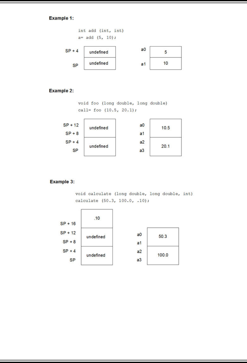
Figure 14-1. Passing Arguments
14.7 Function Return Values
Function return values are returned in registers.
Integral or pointer value are placed in register v0. All floating-point values, regardless of precision, are returned in
floating-point register $f0.
If a function needs to return an actual structure or union – not a pointer to such an object – the called function copies
this object to an area of memory that is reserved by the caller. The caller passes the address of this memory area in
XC32 Compiler for PIC32M
Functions
© 2020 Microchip Technology Inc.
User Guide
DS50002799B-page 158

register $4 when the function is called. The function also returns a pointer to the returned object in register v0.
Having the caller supply the return object’s space allows re-entrance.
14.8 Calling Functions
By default, functions are called using the direct form of the call (jal) instruction. This allows calls to destinations
within a 256 MB segment. This operation can be changed through the use of attributes applied to functions or
command-line options so that a longer, but unrestricted, call is made.
The -mlong-calls option, see 6.7.1 Options Specific to PIC32M Devices, forces a register form of the call to be
employed by default. Generated code is longer, but calls are not limited in terms of the destination address.
The attributes longcall or far can be used with a function definition to always enforce the longer call sequence for
that function. The near attribute can be used with a function so that calls to it use the shorter direct call, even if the -
mlong-calls option is in force.
14.9 Inline Functions
Enter a short description of your concept here (optional).
By declaring a function inline, you can direct the compiler to integrate that function’s code into the code for its
callers. This usually makes execution faster by eliminating the function-call overhead. In addition, if any of the actual
argument values are constant, their known values may permit simplifications at compile time, so that not all of the
inline function’s code needs to be included. The effect on code size is less predictable. Machine code may be larger
or smaller with inline functions, depending on the particular case.
Note: Function inlining will only take place when the function’s definition is visible (not just the prototype). In order to
have a function inlined into more than one source file, the function definition may be placed into a header file that is
included by each of the source files.
To declare a function inline, use the inline keyword in its declaration, like this:
inline int
inc (int *a)
{
(*a)++;
}
(If you are using the -traditional option or the -ansi option, write __inline__ instead of inline.) You can
also make all “simple enough” functions inline with the command-line option -finline-functions. The compiler
heuristically decides which functions are simple enough to be worth integrating in this way, based on an -estimate of
the function’s size.
Note: The inline keyword will only be recognized with -finline or optimizations enabled.
Certain usages in a function definition can make it unsuitable for inline substitution. Among these usages are: use of
varargs, use of alloca, use of variable-sized data, use of computed goto and use of nonlocal goto. Using the
command-line option -Winline will warn when a function marked inline could not be substituted, and will give the
reason for the failure.
In compiler syntax, the inline keyword does not affect the linkage of the function.
When a function is both inline and static, if all calls to the function are integrated into the caller and the
function’s address is never used, then the function’s own assembler code is never referenced. In this case, the
compiler does not actually output assembler code for the function, unless you specify the command-line option -
fkeep-inline-functions. Some calls cannot be integrated for various reasons (in particular, calls that precede
the function’s definition cannot be integrated and neither can recursive calls within the definition). If there is a non-
integrated call, then the function is compiled to assembler code as usual. The function must also be compiled as
usual if the program refers to its address, because that can’t be inlined. The compiler will only eliminate inline
functions if they are declared to be static and if the function definition precedes all uses of the function.
XC32 Compiler for PIC32M
Functions
© 2020 Microchip Technology Inc.
User Guide
DS50002799B-page 159

When an inline function is not static, then the compiler must assume that there may be calls from other source
files. Since a global symbol can be defined only once in any program, the function must not be defined in the other
source files, so the calls therein cannot be integrated. Therefore, a non-static inline function is always compiled on
its own in the usual fashion.
If you specify both inline and extern in the function definition, then the definition is used only for inlining. In no
case is the function compiled on its own, not even if you refer to its address explicitly. Such an address becomes an
external reference, as if you had only declared the function and had not defined it.
This combination of inline and extern has a similar effect to a macro. Put a function definition in a header file with
these keywords and put another copy of the definition (lacking inline and extern) in a library file. The definition in
the header file will cause most calls to the function to be inlined. If any uses of the function remain, they will refer to
the single copy in the library.
XC32 Compiler for PIC32M
Functions
© 2020 Microchip Technology Inc.
User Guide
DS50002799B-page 160

15. Interrupts
Interrupt processing is an important aspect of most microcontroller applications. Interrupts may be used to
synchronize software operations with events that occur in real time. When interrupts occur, the normal flow of
software execution is suspended, and special functions are invoked to process the event. At the completion of
interrupt processing, previous context information is restored and normal execution resumes.
PIC32 devices support multiple interrupts, from both internal and external sources. The devices allow high-priority
interrupts to override any lower priority interrupts that may be in progress.
The compiler provides full support for interrupt processing in C/C++ or inline assembly code. This section presents an
overview of interrupt processing.
15.1 Interrupt Operation
The compiler incorporates features allowing interrupts to be fully handled from C/C++ code. Interrupt functions are
often called interrupt handlers or Interrupt Service Routines (ISRs).
Each interrupt source typically has a control bit in an SFR which can disable that interrupt source. Check your device
data sheet for full information how your device handles interrupts.
Interrupt code is the name given to any code that executes as a result of an interrupt occurring. Interrupt code
completes at the point where the corresponding return from interrupt instruction is executed. This contrasts with
main-line code, which, for a freestanding application, is usually the main part of the program that executes after
Reset.
15.2 Writing an Interrupt Service Routine
An interrupt handler function is different than an ordinary function in that it handles the context save and restore to
ensure that upon return from interrupt, the program context is maintained. A different code sequence is used to return
from these functions as well.
Several attributes can be used to ensure that the compiler generates the correct code for an ISR. Macros are
provided so that this is easier to accomplish, see the following sections.
There are several actions that the compiler needs to take to generate an interrupt service routine. The compiler has
to be told to use an alternate form of return code. The function also needs to be linked to the interrupt vector. All ISRs
must use either the MIPS32
®
r2 or the microMIPS
™
ISA modes. Apply the 'nomips16' function attribute to each
interrupt function.
Note: For devices that support multiple Instruction Set Architecture (ISA) modes, there may be a configuration bit
that determines which mode the device uses for an exception/interrupt. If your device is configured to use the
microMIPS ISA on interrupt, be sure to apply the micromips function attribute to your interrupt function. Consult
your the data sheet for your target device to determine if it supports handling exceptions and interrupts in an alternate
ISA mode.
An interrupt function must be declared as type void and may not have parameters. This is the only function
prototype that makes sense for an interrupt function since they are never directly called in the source code.
Interrupt functions must not be called directly from C/C++ code (due to the different return instruction that is used),
but they themselves may call other functions, both user-defined and library functions, but be aware that this may use
additional registers which will need to be saved and restored by the context switch code.
A function is marked as an interrupt handler function, or ISR, via either the interrupt attribute or the interrupt
pragma*. While each method is functionally equivalent to the other, the interrupt attribute is more commonly used
and therefore the recommended method. The interrupt is specified as handling interrupts of a specific priority level or
for operating in single vector mode.
For all interrupt vectors without specific handlers, a default interrupt handler will be installed. The default interrupt
handler is supplied by the libpic32.a library and will cause a debug breakpoint and reset the device. An application
may override the default handler and provide an application-specific default interrupt handler by declaring an interrupt
function with the name _DefaultInterrupt.
XC32 Compiler for PIC32M
Interrupts
© 2020 Microchip Technology Inc.
User Guide
DS50002799B-page 161

Note: * Pre-processor macros are not expanded in pragma directives.
15.2.1 Interrupt Attribute
__attribute__((interrupt([IPLn[SRS|SOFT|AUTO]])))
Where n is in the range of 0..7, inclusive.
Use the interrupt attribute to indicate that the specified function is an interrupt handler. The compiler generates
function entry and exit sequences suitable for use in an interrupt handler when this attribute is present. The
generated code preserves context by either using a shadow register set (SRS) or using generated software
instructions (SOFT) to push context onto the stack. See the example below for an interrupt attribute.
Note: Some PIC32 target devices allow the exception/interrupt code to be in either the MIPS32
®
or microMIPS
™
ISA mode via a device configuration bit (BOOTISA). On these devices, if your BOOTISA bit is set to microMIPS
mode, add the 'micromips' attribute to your interrupt function. If your BOOTISA bit is set to MIPS32 mode, add the
'nomicromips' attribute to your interrupt function. See your device data sheet for more information on this
configuration bit.
Example 15-1. Interrupt Attribute
void __attribute__((interrupt(IPL7SRS))) bambam (void);
Many PIC32 devices allow us to specify, via configuration-bit settings, which interrupt priority level will use the
shadow register set (for example, #pragma config FSRSSEL=PRIORITY_7). Refer to the device data sheet to
determine if your PIC32 target device supports this feature. This means we must specify which context-saving
mechanism to use for each interrupt handler. The compiler will generate interrupt function prologue and epilogue
code utilizing shadow register context saving for the IPLnSRS Interrupt Priority Level (IPL) specifier. It will use
software context saving for the IPLnSOFT IPL specifier.
Other PIC32 variants may have 8 register sets (1 standard set and 7 shadow register sets) meaning that there are
enough shadow register sets for every interrupt priority level. Therefore, you should use the IPLnSRS IPL specifier
for every interrupt service routine on these device variants.
Note: Application code is responsible for applying the correct IPL specifier value to each ISR. The interrupt source’s
priority level must match the ISR’s IPL value (for example, IPLnSRS) or the interrupt will not be handled correctly.
Mismatching priority levels may result in critical runtime problems such as a stack overflow that overwrites data
memory. This can include corruption of memory reserved for use by the Debug Executive, causing the debug tool to
behave erratically.
The compiler also supports an IPLnAUTO IPL specifier that uses the run-time value in SRSCTL to determine whether
it should use software or SRS context-saving code. The compiler defaults to using IPLnAUTO when the IPL specifier
is omitted from the interrupt() attribute.
For devices that do not support a shadow register set for interrupt context saving, use IPLnSOFT for all interrupt
handlers.
Note: SRS has the shortest latency and SOFT has a longer latency due to registers saved on the stack. AUTO adds a
few cycles to test if SRS or SOFT should be used.
For IPL7(SRS | SOFT | AUTO), the compiler assumes that nothing can interrupt priority 7. This means that there
is no reason to save EPC or SRSCtl and that global disabling of interrupts is unnecessary.
The IPLnSAVEALL interrupt priority specifier can be used with the interrupt attribute. Use this specifier in place of
IPLnSOFT to force software context saving of all software-saved general registers even if they are not used within
the Interrupt Service Routine (ISR). This attribute can be useful for some RTOS implementations.
The keep_interrupts_masked attribute can be used to modify the behavior of an interrupt handler. The attribute
keeps interrupts masked for the whole function. Without this attribute, the XC32 compiler re-enables interrupts for as
much of the function as it can. By keeping interrupts masked, support for nested interrupts is disables. Users can re-
enable them as necessary in their own code.
The attribute keep_interrupts_masked can be combined with the interrupt attribute. This attribute causes the
Interrupt Service Routine (ISR) prologue code to not re-enable interrupts. Application code may then choose whether
and when to re-enable interrupts in the ISR.
XC32 Compiler for PIC32M
Interrupts
© 2020 Microchip Technology Inc.
User Guide
DS50002799B-page 162

15.2.2 Interrupt Pragma
Note: The interrupt pragma is provided only for compatibility when porting code from other compilers. The
interrupt function attribute is the preferred and more common way to write an interrupt service routine.
# pragma interrupt function-name IPLn[AUTO|SOFT|SRS] [vector [@]vector-number [, vector-
number-list]]
# pragma interrupt function-name single [vector [@] 0
Where n is in the range of 0..7, inclusive.
The IPLn[AUTO|SOFT|SRS] IPL specifier may be all uppercase or all lowercase.
The function definition for a handler function indicated by an interrupt pragma must follow in the same translation unit
as the pragma itself.
The interrupt attribute will also indicate that a function definition is an interrupt handler. It is functionally equivalent
to the interrupt pragma.
For example, the definitions of foo below both indicate that it is an interrupt handler function for an interrupt of
priority 4 that uses software context saving.
#pragma interrupt foo IPL4SOFT
void foo (void)
is functionally equivalent to
void __attribute__ ((interrupt(IPL4SOFT))) foo (void)
15.2.3 __ISR Macros
The <sys/attribs.h> header file provides macros intended to simplify the application of attributes to interrupt
functions. There are also vector macros defined in the processor header files. (See the appropriate header file in the
compiler’s /pic32mx/include/proc directory.)
Note: Some PIC32 target devices allow the exception/interrupt code to be in either the MIPS32
®
or microMIPS
™
ISA mode via a device configuration bit (BOOTISA). On these devices, if your BOOTISA bit is set to microMIPS
mode, add the 'micromips' attribute to your interrupt function. If your BOOTISA bit is set to MIPS32 mode, add the
'nomicromips' attribute to your interrupt function. See your device data sheet for more information on this
configuration bit.
__ISR(V, IPL)
Use the __ISR(v, IPL) macro to assign the vector-number location and associate it with the specified IPL. This
will place a jump to the interrupt handler at the associated vector location. This macro also applies the nomips16
attribute since PIC32 devices require that interrupt handlers must use the MIPS32 instruction set.
The following example creates an interrupt handler function for the core timer interrupt that has an interrupt priority
level of two. The compiler places a dispatch function at the associated vector location. To reach this function, the core
timer interrupt flag and enable bits must be set, and the interrupt priority should be set to a level of two. The compiler
generates software context-saving code for this handler function.
Example 15-2. Core Timer Vector, IPL2SOFT
#include <xc.h>
#include <sys/attribs.h>
void __ISR(_CORE_TIMER_VECTOR, IPL2SOFT) CoreTimerHandler(void);
The example below creates an interrupt handler function for the core software interrupt 0 that has an interrupt priority
level of three. The compiler places a dispatch function at the associated vector location. To reach this function, the
core software interrupt flag and enable bits must be set, and the interrupt priority should be set to a level of three. The
device configuration fuses must assign Shadow Register Set 1 to interrupt priority level three. The compiler
generates code that assumes that register context will be saved in SRS1.
XC32 Compiler for PIC32M
Interrupts
© 2020 Microchip Technology Inc.
User Guide
DS50002799B-page 163

Example 15-3. Core Software 0 Vector, IPL3SRS
#include <xc.h>
#include <sys/attribs.h>
void __ISR(_CORE_SOFTWARE_0_VECTOR,IPL3SRS) CoreSoftwareInt0Handler(void);
The example below creates an interrupt handler function for the core software interrupt 1 that has an interrupt priority
level of zero. The compiler places a dispatch function at the associated vector location. To reach this function, the
core software interrupt 1 flag and enable bits must be set, and the interrupt priority should be set to a level of zero.
The compiler generates code that determines at run time whether software context saving is required.
Example 15-4. Core Software 1 Vector, IPL0AUTO
#include <xc.h>
#include <sys/attribs.h>
void __ISR(_CORE_SOFTWARE_1_VECTOR, IPL0AUTO) CoreSoftwareInt1Handler(void);
The next example is functionally equivalent to Example 14-4. Because the IPL specifier is omitted, the compiler
assumes IPL0AUTO.
Example 15-5. Core Software 1 Vector, Default
#include <xc.h>
#include <sys/attribs.h>
void __ISR(_CORE_SOFTWARE_1_VECTOR) _CoreSoftwareInt1Handler(void);
__ISR_AT_VECTOR(v, IPL)
Use the __ISR_AT_VECTOR(v, IPL) to place the entire interrupt handler at the vector location and associate it
with the software-assigned interrupt priority. Application code is responsible for making sure that the vector spacing is
set to accommodate the size of the handler. This macro also applies the nomips16 attribute since ISR functions are
required to be MIPS32.
The following example creates an interrupt handler function for the core timer interrupt that has an interrupt priority
level of two. The compiler places the entire interrupt handler at the vector location. It does not use a dispatch
function. To reach this function, the core timer interrupt flag and enable bits must be set, and the interrupt priority
should be set to a level of two. The compiler generates software context-saving code for this handler function.
Example 15-6. Core Timer Vector, IPL2SOFT
#include <xc.h>
#include <sys/attribs.h>
void __ISR_AT_VECTOR(_CORE_TIMER_VECTOR, IPL2SOFT) CoreTimerHandler(void);
INTERRUPT-VECTOR MACROS
Each processor-support header file provides a macro for each interrupt-vector number (for example, /pic32mx/
include/proc/p32mx360f512l.h. See the appropriate header file in the compiler install directory). When used
in conjunction with the __ISR() macro provided by the sys\attribs.h header file, these macros help make an
Interrupt Service Routine easier to write and maintain.
The example below creates an interrupt handler function for the Timer 1 interrupt that has an interrupt priority level of
seven. The compiler places a dispatch function at the vector location associated with macro _TIMER_1_VECTOR as
defined in the device-specific header file. To reach this function, the Timer 1 interrupt flag and enable bits must be
set, and the interrupt priority should be set to a level of seven. For devices that allow assignment of shadow registers
to specific IPL values, the device Configuration bit settings must assign Shadow Register Set 1 to interrupt priority
level seven. The compiler generates code that assumes that register context will be saved in SRS1.
XC32 Compiler for PIC32M
Interrupts
© 2020 Microchip Technology Inc.
User Guide
DS50002799B-page 164

Example 15-7. Interrupt-Vector with Handler
#include <xc.h>
#include <sys/attribs.h>
void __ISR (_TIMER_1_VECTOR, IPL7SRS) Timer1Handler (void);
15.3 Associating a Handler Function with an Exception Vector
For PIC32 devices, each interrupt source is mapped to an exception vector, as specified in the device data sheet. For
devices with a constant vector spacing, a default of four words of space are reserved at each vector address for a
dispatch to the handler function for that exception source. For devices with a variable vector spacing, the default
linker script adjusts each vector's spacing for the size of the designated interrupt function.
An interrupt handler function can be associated with an interrupt vector either as the target of a dispatch function
located at the exception vector address, or as being located directly at the exception vector address. A single handler
function can be the target of multiple dispatch functions.
The association of a handler function to one or more exception vector addresses is specified via a vector attribute on
the function declaration. For compatibility purposes, you may also associate a handler function to a vector address
using a clause of the interrupt pragma, a separate vector pragma, or a vector attribute on the function declaration.
15.3.1 Vector Attribute
A handler function can be associated with one or more exception vector addresses via an attribute. The at_vector
attribute indicates that the handler function should itself be placed at the exception vector address. The vector
attribute indicates that a dispatch function should be created at the exception vector address(es) which will transfer
control to the handler function.
For example, the following declaration specifies that function foo will be created as an interrupt handler function of
priority four. foo will be located at the address of exception vector 54.
void __attribute__ ((interrupt(IPL4SOFT))) __attribute__ ((at_vector(54))) foo void);
The following declaration specifies that function foo will be created as an interrupt handler function of priority four.
Define dispatch functions targeting foo at exception vector addresses 52 and 53.
void __attribute__ ((interrupt(IPL4SOFT))) __attribute__ ((vector(53, 52))) foo void)
Handler functions that are linked directly to the vector will be executed faster. Although the vector spacing can be
adjusted, there is limited space between vectors and linking a substantial handler function directly at a vector may
cause it to overlap the higher vector locations, preventing their use. In such situations, using a dispatch function is a
safer option.
The newer devices family features variable offsets for vector spacing. The compiler and linker work together to treat
the OFFnnn SFRs as initialized data so that they are initialized at startup. This means there is no need for application
code to initialize the OFFnnn SFRs. This also means that it is often more efficient to place the ISR within the vector
table rather than using a dispatch function.
Example 15-8. Example Interrupt Service Routine
#include <xc.h>
#include <sys/attribs.h>
void
__ISR_AT_VECTOR(_CORE_TIMER_VECTOR, IPL7SRS)
CoreTimerHandler(void)
{
// ISR code here
}
XC32 Compiler for PIC32M
Interrupts
© 2020 Microchip Technology Inc.
User Guide
DS50002799B-page 165

15.3.2 Interrupt-Pragma Vector Clause
Note: The interrupt pragma and its vector clause are provided only for compatibility when porting code from other
compilers. The vector function attribute is the preferred way to associate a handler function to an exception vector
address.
The interrupt pragma has an optional vector clause following the priority specifier.
# pragma interrupt function-nameIPL-specifier [vector [@]vector-number [, vector-
number-list]]
A dispatch function targeting the specified handler function will be created at the exception vector address for the
specified vector numbers. If the first vector number is specified with a preceding “@” symbol, the handler function
itself will be located there directly.
For example, the following pragma specifies that function foo will be created as an interrupt handler function of
priority four. foo will be located at the address of exception vector 54. A dispatch function targeting foo will be
created at exception vector address 34.
#pragma interrupt foo IPL4AUTO vector @54, 34
The following pragma specifies that function bar will be created as an interrupt handler function of priority five. bar
will be located in general purpose program memory (.text section). A dispatch function targeting bar will be created
at exception vector address 23.
#pragma interrupt bar IPL5SOFT vector 23
15.3.3 Vector Pragma
Note: The vector pragma is provided only for compatibility when porting code from other compilers. The vector
function attribute is the preferred way to associate a handler function to an exception vector address.
The vector pragma creates one or more dispatch functions targeting the indicated function. For target functions
specified with the interrupt pragma, this functions as if the vector clause had been used. The target function of a
vector pragma can be any function, including external functions implemented in assembly or by other means.
# pragma vector function-name vector vector-number [, vector-number-list]
The following pragma defines a dispatch function targeting foo at exception vector address 54.
#pragma vector foo 54
15.4 Exception Handlers
The PIC32 devices also have exception vectors for non-interrupt exceptions. These exceptions are grouped into
bootstrap exceptions and general exceptions.
15.4.1 Bootstrap Exception
A Reset exception is any exception which occurs while bootstrap code is running (Status
BEV
=1). All Reset
exceptions are vectored to 0xBFC00380.
At this location, the 32-bit toolchain places a branch instruction targeting a function named
_bootstrap_exception_handler(). In the standard library, a default weak version of this function is provided,
which merely causes a software Reset. When compiling for in-circuit debugging or emulation, the default
implementation of _bootstrap_exception_handler will first cause a software breakpoint and then a software
Reset. If the user application provides an implementation of _bootstrap_exception_handler(), that
implementation will be used instead.
15.4.2 General Exception
A general exception is any non-interrupt exception which occurs during program execution outside of bootstrap code
(Status
BEV
=0). General exceptions are vectored to offset 0x180 from EBase.
At this location, the 32-bit toolchain places a branch instruction targeting a function named
_general_exception_context(). The provided implementation of this function saves context, calls an
XC32 Compiler for PIC32M
Interrupts
© 2020 Microchip Technology Inc.
User Guide
DS50002799B-page 166

application handler function, restores context and performs a return from the exception instruction. The context saved
is the hi and lo registers, and all General Purpose Registers except s0-s8, which are defined to be preserved by
all called functions and so are not necessary to actively save here again.
void _general_exception_handler (void);
A weak default implementation of _general_exception_handler() is provided in the standard library which
merely causes a software Reset. When compiling for in-circuit debugging or emulation, the default implementation of
_general_exception_handler will first cause a software breakpoint and then a software Reset. If the user
application provides an implementation of _general_exception_handler(), that implementation will be used
instead.
15.4.3 Simple TLB Refill Exception
During an instruction fetch or data access, a TLB refill exception occurs when no TLB entry matches a reference to a
mapped address space and the EXL bit is 0 in the Status register. Note that this is distinct from the case in which an
entry matches, but has the valid bit off. In that case, a TLB Invalid exception occurs.
void _simple_tlb_refill_exception_handler(void);
A weak default implementation of _simple_tlb_refill_exception_handler() is provided which merely
causes a software Reset.
When compiling for in-circuit debugging or emulation, the default implementation of
_simple_tlb_refill_exception_handler will first cause a software breakpoint and then a software Reset.
15.4.4 Cache Error Exception
A cache-error exception occurs when an instruction or data reference detects a cache tag or data error. This
exception is not maskable. To avoid disturbing the error in the cache array the exception vector is to an unmapped,
uncached address. This exception is precise.
void _cache_err_exception_handler(void);
A weak default implementation of _cache_err_exception_handler() is provided which merely causes a
software Reset. When compiling for in-circuit debugging or emulation, the default implementation of
_cache_err_exception_handler will first cause a software breakpoint and then a software Reset.
15.5 Interrupt Service Routine Context Switching
The standard calling convention for C/C++ functions will already preserve zero, s0-s7, gp, sp, and fp. k0 and k1
are used by the compiler to access and preserve non-GPR context, but are always accessed atomically (that is, in
sequences with global interrupts disabled), so they need not be preserved actively. A handler function will actively
preserve the a0-a3, t0-t9, v0, v1 and ra registers in addition to the standard registers.
An interrupt handler function will also actively save and restore processor status registers that are utilized by the
handler function. Specifically, the EPC, SR, hi and lo registers are preserved as context. All available DSP
accumulators are preserved as necessary.
In addition, if a DSP accumulator register is preserved, the DSP Control register is also preserved.
Handler functions may use a shadow register set to preserve the General Purpose Registers, enabling lower latency
entry into the application code of the handler function. On some devices, the shadow register set is assigned to an
interrupt priority level (IPL) using the device Configuration bit settings (for example, #pragma config
FSRSSEL=PRIORITY_6). While on other devices, the shadow register set may be hard wired to IPL7. Consult the
target device’s data sheet for more information on the shadow register set.
15.5.1 Context Restoration
Any objects saved by software are automatically restored by software before the interrupt function returns. The order
of restoration is the reverse to that used when context is saved.
XC32 Compiler for PIC32M
Interrupts
© 2020 Microchip Technology Inc.
User Guide
DS50002799B-page 167

15.6 Latency
There are two elements that affect the number of cycles between the time the interrupt source occurs and the
execution of the first instruction of your ISR code. These are:
• Processor Servicing of Interrupt – The amount of time it takes the processor to recognize the interrupt and
branch to the first address of the interrupt vector. To determine this value, refer to the processor data sheet for
the specific processor and interrupt source being used.
• ISR Code – The compiler saves the registers that were used by the ISR. Moreover, if the ISR calls an ordinary
function, then the compiler will save all the working registers, even if they are not all used explicitly in the ISR
itself. This must be done, because the compiler cannot know, in general, which resources are used by the called
function.
15.7 Nesting Interrupts
Interrupts may be nested. The interrupt priority scheme implemented in the PIC32 architecture allows you to specify
which interrupt sources may be interruptible by others. See your device data sheet for explicit details on interrupt
operation.
The compiler Interrupt Service Routine prologue code automatically re-enables interrupts by default.
15.8 Enabling/Disabling Interrupts
The following builtin functions inspect or manipulate the current CPU interrupt state:
unsigned int __builtin_get_isr_state(void)
void __builtin_set_isr_state(unsigned int)
unsigned int __builtin_disable_interrupts(void)
void __builtin_enable_interrupts(void)
15.9 ISR Considerations
There are a few things to consider when writing an interrupt service routine.
As with all compilers, limiting the number of registers used by the interrupt function, or any functions called by the
interrupt function, may result in less context switch code being generated and executed by the compiler, see 15.6
Latency. Keeping interrupt functions small and simple will help you achieve this.
When interrupt latency is a concern, avoid calling other functions from your ISR. You may be able to replace a
function call with a volatile flag that is handled by your application's main control loop.
XC32 Compiler for PIC32M
Interrupts
© 2020 Microchip Technology Inc.
User Guide
DS50002799B-page 168

16. Main, Runtime Start-up and Reset
When creating C/C++ code, there are elements that are required to ensure proper program operation: a main
function must be present; start-up code will be needed to initialize and clear variables and setup registers and the
processor; and Reset conditions will need to be handled.
16.1 The Main Function
The identifier main is special. It must be used as the name of a function that will be the first function to execute in a
program. You must always have one and only one function called main in your programs. Code associated with
main, however, is not the first code to execute after Reset. Additional code provided by the compiler and known as
the runtime start-up code is executed first and is responsible for transferring control to the main() function.
16.2 Runtime Start-Up Code
A C/C++ program requires certain objects to be initialized and the processor to be in a particular state before it can
begin execution of its function main(). It is the job of the runtime start-up code to perform these tasks. The runtime
start-up code is executed before main(), but if you require any special initialization to be performed immediately
after Reset, you should use the On Reset feature described in 16.3 The On Reset Routine.
The PIC32 start-up code must perform the following:
1. Switch to the selected instruction set (ISA) mode.
2. Jump to NMI handler (_nmi_handler) if an NMI occurred.
3. Initialize stack pointer and heap.
4. Initialize global pointer in all register sets available on the selected target device.
5. Call the application-provided “on reset” procedure (_on_reset).
6. Call the __pic32_init_cache procedure to initialize the L1 cache on target devices that feature an L1
cache.
7. Call the __pic32_tlb_init_ebi_sqi procedure to initialize the TLB on -target devices that use pre-
mapped EBI and SQI external memory regions.
8. Clear uninitialized small bss sections.
9. Initialize data using the linker-generated data-initialization template.
10. If the target device that features a bus matrix and the application uses a RAM function, initialize the bus matrix
for execution from data memory.
11. Initialize the CP0 registers.
12. Enable the DSPr2 engine on target devices that feature it. Also, enable and configure the Floating-Point Unit
(FPU) on devices that feature it.
13. Call the “On Bootstrap” procedure (_on_bootstrap).
14. Change the location of exception vectors.
15. For C++, call the C++ initialization code to invoke all constructors for file-scope static storage objects.
16. Call main().
The following provisions are made regarding the run-time model:
• Kernel mode only
• KSEG1 only
• RAM functions are attributed with __ramfunc__ or __longramfunc__, (defined in sys/attribs.h),
meaning that all RAM functions end up in the .ramfunc section and the function is ramfunc attributed.
16.2.1 Switch to the Selected Instruction Set (ISA) Mode
Some PIC32 MCUs support both the MIPS32 and microMIPS Instruction Set Architecture (ISA) modes. The
microMIPS instruction set delivers the same functionality as the MIPS32 ISA, with the added benefit of smaller code
size.
XC32 Compiler for PIC32M
Main, Runtime Start-up and Reset
© 2020 Microchip Technology Inc.
User Guide
DS50002799B-page 169

Devices that support both the MIPS32 and microMIPS ISA modes use the BOOTISA configuration bit in a device
Configuration Word to determine the ISA mode on boot. The device can be configured to boot to either the MIPS32
or the microMIPS ISA mode. See the target-device data sheet for more information on the BOOTISA bit.
The microMIPS ISA supplies assembler-source code compatibility with MIPS32 instead of binary compatibility.
Because of this, the XC32 toolchain provides a copy of the runtime start-up code compiled for the MIPS32 ISA as
well as a copy compiled for the microMIPS ISA. The toolchain determines which copy to link based on the presence
of the -mmicromips command-line option. In the MPLAB X IDE project properties, select xc32-ld >Option category:
Libraries> "Link microMIPS compressed startup code and libraries" to get the -mmicromips option.
For added flexibility, the default start-up code attempts to ensure that the linked Precompiled mode matches the
current ISA mode at runtime. To enable this, a binary code sequence is required that can be run in either instruction
set and change code paths, depending on the instruction set that is being used.
The following binary sequence achieves this goal:
0x1000wxyz // where w,x,y,z represent hexadecimal digits
0x00000000
For the MIPS32 instruction set, this binary sequence is interpreted as:
// branch to location of more MIPS32 instructions
BEQ $0, $0, wxyz
NOP
For the microMIPS instruction set, this binary sequence is interpreted as:
ADDI32 $0, $0, wxyz // do nothing
NOP // fall through to more microMIPS instructions
In the default runtime startup-code, we place this binary sequence at the _reset symbol, which is then located at the
reset vector by the default linker script. We follow this binary sequence with a jal _startup to jump to the
remainder of the startup code.
This sequence is included only for devices that support both the MIPS32 and microMIPS ISA modes.
On PIC32M devices, bit 0 of the address indicates the ISA mode. When this bit is clear, the device is running in
MIPS32 Mode. When this bit is set, the device is running in either MIPS16 or microMIPS mode, depending on the
device core. This means that if you execute a hard-coded jump, bit 0 must be set to the appropriate value for your
target function. Hard-coded jumps are most commonly seen when jumping from a bootloader to a bootloaded
application.
16.2.2 Jump to NMI Handler (_nmi_handler) if an NMI Occurred
If a Non-Maskable Interrupt (NMI) caused entry to the Reset vector, which is located at 0xBFC00000 on PIC32M
MIPS cores, the startup code’s _reset function jumps to an NMI Handler procedure named _nmi_handler. A
weak version of the NMI handler procedure is provided that performs an ERET.
To override the default NMI Handler with an application-specific handler, use an assembly-code .S file to create a
routine named __nmi_handler. This routine must be written in assembly code because the startup code calls this
routine before the C runtime environment is initialized. The __nmi_handler routine must either use only the k0, k1
CPU registers or it must save context before using other registers.
16.2.3 Initialize Stack Pointer and Heap
The Stack Pointer (sp) register must be initialized in the start-up code. To enable the start-up code to initialize the sp
register, the linker must initialize a variable which points to the end of KSEG0/KSEG1 data memory.
Note: The end of data memory is different based on whether RAM functions exist. If RAM functions exist, then part
of the DRM must be configured for the kernel program to contain the RAM functions, and the Stack Pointer is located
one word prior to the beginning of the DRM kernel program boundary address. If RAM functions do not exist, then the
Stack Pointer is located at the true end of DRM.
The linker allocates the stack to KSEG0 on devices featuring an L1 data cache. It allocates the stack to KSEG1 on
devices that do not have an L1 cache.
XC32 Compiler for PIC32M
Main, Runtime Start-up and Reset
© 2020 Microchip Technology Inc.
User Guide
DS50002799B-page 170
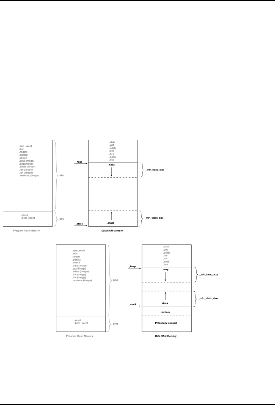
This variable is named _stack. The user can change the minimum amount of stack space allocated by providing the
command line option --defsym _min_stack_size=N to the linker. _min_stack_size is provided by the linker
script with a default value of 1024. On a similar note, the user may wish to utilize a heap with their application. While
the start-up code does not need to initialize the heap, the standard C libraries (sbrk) must be made aware of the
heap location and its size. The linker creates a variable to identify the beginning of the heap. The location of the heap
is the end of the utilized KSEG0/KSEG1 data memory.
The linker allocates the heap to KSEG0 on devices that have an L1 cache. It allocates the heap to KSEG1 on
devices that do not have an L1 cache.
This variable is named _heap. A user can change the minimum amount of heap space allocated by providing the
command line option --defsym _min_heap_size=M to the linker. If the heap is used when the heap size is set to
zero, the behavior is the same as when the heap usage exceeds the minimum heap size. Namely, it overflows into
the space allocated for the stack.
The heap and the stack use the unallocated KSEG0/KSEG1 data memory, with the heap starting from a low address
in KSEG0/KSEG1 data memory, and growing upwards towards the stack while the stack starts at a higher address in
KSEG1 data memory and grows downwards towards the heap. The linker attempts to allocate the heap and stack
together in the largest gap of memory available in the KSEG0/KSEG1 data memory region. If enough space is not
available based on the minimum amount of heap size and stack size requested, the linker issues an error.
Figure 16-1. Stack and Heap Layout
Figure 16-2. Stack and Heap Layout with RAM Functions
The linker must then group all of the above input sections together. This grouping is handled by the default linker
script. The run-time start-up code must initialize the gp register to point to the “middle” of this output section. To
enable the start-up code to initialize the gp register, the linker script must initialize a variable which is 32 KB from the
start of the output section containing the “small” variables and constants. This variable is named _gp (to match core
linker scripts). Besides being initialized in the standard GPR set, the Global Pointer must also be initialized in the
register shadow set.
XC32 Compiler for PIC32M
Main, Runtime Start-up and Reset
© 2020 Microchip Technology Inc.
User Guide
DS50002799B-page 171

16.2.4 Initialize Global Pointer
The compiler toolchain supports Global Pointer (gp) relative addressing. Loads and stores to data residing within
32KB of either side of the address stored in the gp register can be performed in a single instruction using the gp
register as the base register. Without the Global Pointer, loading data from a static memory area takes two
instructions – one to load the Most Significant bits of the 32-bit constant address computed by the compiler/linker and
one to do the data load.
To utilize gp-relative addressing, the compiler and assembler must group all of the “small” variables and constants
into one of the following sections:
.lit4. lit8
.sdata. sbss
.sdata.* sbss.*
.gnu.linkonce.s.* .gnu.linkonce.sb.*
The linker must then group all of the above input sections together. This grouping is handled by the default linker
script. The run-time start-up code must initialize the gp register to point to the “middle” of this output section. To
enable the start-up code to initialize the gp register, the linker script must initialize a variable which is 32 KB from the
start of the output section containing the “small” variables and constants. This variable is named _gp (to match core
linker scripts).
Some PIC32 MCUs have more than one register set. The additional register sets can be used as interrupt shadow
register sets. The Global Pointer must be initialized in each of the register sets. The default start-up code does this by
looping through each of the register sets.
In the loop, the CP0 SRSCtl register's PSS field must be set to the shadow set in which to initialize the global pointer.
In the source code, we start with the highest register set, as defined by the PIC32_SRS_SET_COUNT macro, and
work down to zero. By initializing the global pointer in the previous set as iterate through the register sets, we initialize
the register in each of the sets on the device.
16.2.5 Initialize of Clear Variable and RAM Functions Using the Data-Initialization Template
Those non-auto objects which are not initialized must be cleared before execution of the program begins. This task
is also performed by the runtime start-up code.
Uninitialized variables are those which are not auto objects and which are not assigned a value in their definition, for
example output in the following example:
int output;
int main(void) { ...
Such uninitialized objects will only require space to be reserved in RAM where they will reside and be accessed
during program execution (runtime).
There are two uninitialized data sections—.sbss and .bss. The .sbss section is a data segment containing
uninitialized variables less than or equal to n bytes where n is determined by the -Gn command line option.
The .bss section is a data segment containing uninitialized variables not included in .sbss.
Another task of the runtime start-up code is to ensure that any initialized variables contain their initial value before the
program begins execution. Initialized variables are those which are not auto objects and which are assigned an
initial value in their -definition, for example input in the following example:
int input = 88;
int main(void) { ...
Such initialized objects have two components: their initial value (0x0088 in the above example) stored in program
memory (that is, placed in the HEX file), and space for the -variable reserved in RAM, which will reside and be
accessed during program execution -(runtime).
The runtime start-up code will copy all the blocks of initial values from program memory to RAM so the variables will
contain the correct values before main is executed.
XC32 Compiler for PIC32M
Main, Runtime Start-up and Reset
© 2020 Microchip Technology Inc.
User Guide
DS50002799B-page 172

Since auto objects are dynamically created, they require code to be positioned in the function in which they are
defined to perform their initialization. It is possible that the initial value of an auto object may change on each
instance of the function and so the initial values cannot be stored in program memory and copied. As a result,
initialized auto objects are not considered by the runtime start-up code, but are instead initialized by assembly code
in each function output.
Variables whose contents should be preserved over a Reset should be qualified with the persistent attribute, see
9.9 Standard Type Qualifiers. Such variables are linked at a different area of memory and are not altered by the
runtime start-up code in any way.
Four initialized data sections exist:.sdata, .data, .lit4, and .lit8. The .sdata section is a data segment
containing initialized variables less than or equal to n bytes, where n is determined by the -Gn command line option.
The .data section is a data segment containing initialized variables not included in .sdata. The .lit4 and .lit8
sections contain constants, (usually floating-point) which the assembler stores in memory rather than in the
instruction stream.
Note: Initialized auto variables can impact code performance, particularly if the objects are large in size. Consider
using global or static objects instead.
In order to clear or initialize these sections, the linker creates a data-initialization template, which is loaded into an
output section named .dinit. The linker creates this special .dinit section, allocated in program memory, to hold
the template for the run-time initialization of data. The C/C++ start-up module, crt0.o, interprets this template and
copies initial data values into initialized data sections. This includes sections containing ramfunc attributed
functions. Other data sections (such as .bss) are cleared before the main() function is called. The persistent data
section (.pbss) is not affected. When the application’s main program takes control, all variables and RAM functions
in data memory have been initialized.
The data initialization template contains one record for each output section in data memory. The template is
terminated by a null instruction word. The format of a data initialization record is:
/* data init record */
struct data_record {
char *dst; /* destination address */
unsigned int len; /* length in bytes */
unsigned int format; /* format code */
char dat[0]; /* variable-length data */
};
The first element of the record is a pointer to the section in data memory. The second and third elements are the
section length and format code, respectively. The last element is an optional array of data bytes. For bss-type
sections, no data bytes are required.
Currently supported format codes are:
• 0 – Fill the output section with zeros
• 1 – Copy each byte of data from the data array
16.2.6 Initialize Bus Matrix Registers
On some of the PIC32 MCUs, the bus matrix registers (BMXDKPBA, BMXDUDBA, BMXDUPBA) must be initialized by the
start-up code if any RAM functions exist. The startup code leaves these registers in their state when RAM functions
do not exist in the projects. The linker collects all RAM functions and allocates them to a section of data memory that
is aligned on a 2K-alignment boundary. To determine whether any RAM functions exist in the application, the linker
provides a variable that contains the beginning address of this section. This variable is named _ramfunc_begin.
In addition, the linker provides a 2K-aligned variable required for the boundary register (BMXDKPBA). The variable is
named _bmxdkpba_address. The linker also provides two variables that contains the addresses for the bus matrix
register. These variables are named _bmxdkpba_address, _bmxdudba_address, and _bmxdupba_address.
The linker ensures that RAM functions are aligned to a 2K-alignment boundary as is required by the BMXDKPBA
register.
On other PIC32 devices, no special bus initialization is required to execute RAM functions.
XC32 Compiler for PIC32M
Main, Runtime Start-up and Reset
© 2020 Microchip Technology Inc.
User Guide
DS50002799B-page 173
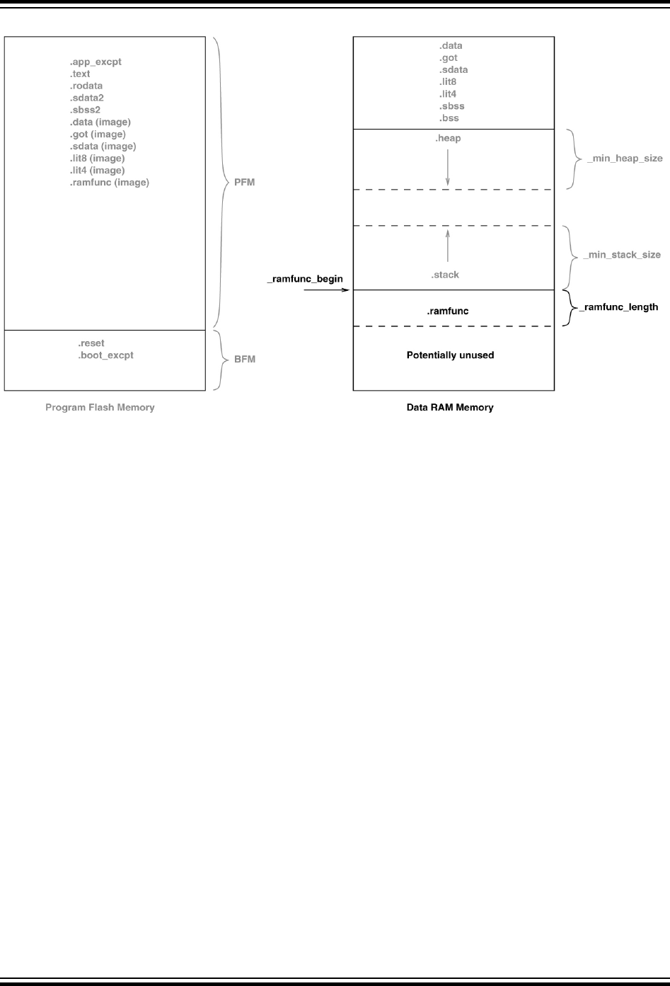
Figure 16-3. Bus Matrix Initialization
Initialize CP0 Registers
The CP0 registers are initialized in the following order:
1. Count register
2. Compare register
3. EBase register
4. IntCtl register
5. Cause register
6. Status register
Hardware Enable Register (HWREna – CP0 Register 7, Select 0)
This register contains a bit mask that determines which hardware registers are accessible via the RDHWR instruction.
Privileged software may determine which of the hardware registers are accessible by the RDHWR instruction. In doing
so, a register may be virtualized at the cost of handling a Reserved Instruction Exception, interpreting the instruction,
and returning the virtualized value. For example, if it is not desirable to provide direct access to the Count register,
access to the register may be individually dis-abled, and the return value can be virtualized by the operating system.
No initialization is performed on this register in the PIC32 start-up code.
Bad Virtual Address Register (BadVAddr – CP0 Register 8, Select 0)
This register is a read-only register that captures the most recent virtual address that caused an Address Error
exception (AdEL or AdES).No initialization is performed on this register in the PIC32 start-up code.
Count Register (Count – CP0 Register 9, Select 0)
This register acts as a timer, incrementing at a constant rate, whether or not an instruction is executed, retired, or any
forward progress is made through the pipeline. The counter increments every other clock if the DC bit in the Cause
register is '0'. The Count register can be written for functional or diagnostic purposes, including at Reset or to
synchronize processors. By writing the CountDM bit in the Debug register, it is possible to control whether the Count
register continues incrementing while the processor is in Debug mode. This register is cleared in the default PIC32
start-up code.
Status Register (Status – CP0 Register 12, Select 0)
XC32 Compiler for PIC32M
Main, Runtime Start-up and Reset
© 2020 Microchip Technology Inc.
User Guide
DS50002799B-page 174

This register is a read/write register that contains the operating mode, Interrupt Enabling, and the diagnostic states of
the processor. Fields of this register combine to create operating modes for the processor.
The following settings are initialized by the default PIC32 start-up code (0b000000000x0xx0?
00000000000000000):
• Access to Coprocessor 0 not allowed in User mode (CU0 = 0)
• User mode uses configured endianess (RE = 0)
• No change to exception vectors location (BEV = no change)
• No change to flag bits that indicate reason for entry to the Reset exception vector (SR, NMI = no change)
• Interrupt masks are cleared to disable any pending interrupt requests (IM7..IM2 = 0, IM1..IM0 = 0)
• Interrupt priority level is 0 (IPL = 0)
• Base mode is Kernel mode (UM = 0)
• Error level is normal (ERL = 0)
• Exception level is normal (EXL = 0)
• Interrupts are disabled (IE = 0)
The DSPr2 engine is enabled on target devices featuring the DSPr2 engine (MX = 1).
The IEEE 754 compliant Floating-Point Unit is enabled for target devices that support the FPU. The FPU is
configured in the FR64 mode, which defines 32 64-bit float-ing-point general registers (FPRs) with all formats
supported in each register (CU1=1) and (FR=1).
Interrupt Control Register (IntCtl – CP0 Register 12, Select 1)
This register controls the expanded interrupt capability added in Release 2 of the Architecture, including vectored
interrupts and support for an external interrupt controller.
This register contains the vector spacing for interrupt handling. The vector spacing portion of this register (bits 9..5) is
initialized with the value of the _vector_spacing symbol by the PIC32 start-up code. All other bits are set to '1'.
Shadow Register Control Register (SRSCtl – CP0 Register 12, Select 2)
This register controls the operation of the GPR shadow sets in the processor. The default startup code uses the
SRSCtl register when it initializes the Global Pointer register in all register sets. However, it restores the original
SRSCtl value after the GP register is initialized.
Shadow Register Map Register (SRSMap – CP0 Register 12, Select 3)
This register contains eight 4-bit fields that provide the mapping from a vector number to the shadow set number to
use when servicing such an interrupt. The values from this register are not used for a non-interrupt exception, or a
non-vectored interrupt (CauseIV = 0 or IntCtlVS = 0). In such cases, the shadow set number comes from
SRSCtlESS. If SRSCtlHSS is zero, the results of a software read or write of this register are UNPREDICTABLE. The
operation of the processor is UNDEFINED if a value is written to any field in this register that is greater than the value
of SRSCtlHSS. The SRSMap register contains the shadow register set numbers for vector numbers 7..0. The same
shadow set number can be established for multiple interrupt vectors, creating a many-to-one mapping from a vector
to a single shadow register set number.
No initialization is performed on this register in the PIC32 start-up code.
Cause Register (Cause – CP0 Register 13, Select 0)
This register primarily describes the cause of the most recent exception. In addition, fields also control software
interrupt requests and the vector through which interrupts are dispatched. With the exception of the DC, IV, and
IP1..IP0 fields, all fields in the Cause register are read-only. Release 2 of the Architecture added optional support
for an External Interrupt Controller (EIC) interrupt mode, in which IP7..IP2 are interpreted as the Requested
Interrupt Priority Level (RIPL).
The following settings are initialized by the PIC32 start-up code:
• Enable counting of Count register (DC = no change)
• Use the special exception vector (16#200) (IV = 1)
• Disable software interrupt requests (IP1..IP0 = 0)
XC32 Compiler for PIC32M
Main, Runtime Start-up and Reset
© 2020 Microchip Technology Inc.
User Guide
DS50002799B-page 175

Exception Program Counter (EPC – CP0 Register 14, Select 0)
This register is a read/write register that contains the address at which processing resumes after an exception has
been serviced. All bits of the EPC register are significant and must be writable. For synchronous (precise) exceptions,
the EPC contains one of the following:
• The virtual address of the instruction that was the direct cause of the exception
• The virtual address of the immediately preceding branch or jump instruction, when the exception causing
instruction is a branch delay slot and the Branch Delay bit in the Cause register is set.
On new exceptions, the processor does not write to the EPC register when the EXL bit in the Status register is set;
however, the register can still be written via the MTC0 instruction.
No initialization is performed on this register in the PIC32 start-up code.
Processor Identification Register (PRId – CP0 Register 15, Select 0)
This register is a 32-bit read-only register that contains information identifying the manufacturer, manufacturer
options, processor identification, and revision level of the processor.
No initialization is performed on this register in the PIC32 start-up code.
Exception Base Register (EBase – CP0 Register 15, Select 1)
This register is a read/write register containing the base address of the exception vectors used when StatusBEV
equals 0, and a read-only CPU number value that may be used by software to distinguish different processors in a
multi-processor system. The EBase register provides the ability for software to identify the specific processor within a
multi-processor system, and allows the exception vectors for each processor to be different, especially in systems
composed of heterogeneous processors. Bits 31..12 of the EBase register are concatenated with zeros to form the
base of the exception vectors when StatusBEV is 0. The exception vector base address comes from fixed defaults
when StatusBEV is 1, or for any EJTAG Debug exception. The Reset state of bits 31..12 of the EBase register
initialize the exception base register to 16#8000-0000, providing backward compatibility with Release 1
implementations. Bits 31..30 of the EBase register are fixed with the value 2#10 to force the exception base address
to be in KSEG0 or KSEG1 unmapped virtual address segments.
If the value of the exception base register is to be changed, this must be done with StatusBEV equal 1. The
operation of the processor is UNDEFINED if the Exception Base field is written with a different value when
StatusBEV is 0.
Combining bits 31..30 with the Exception Base field allows the base address of the exception vectors to be placed at
any 4K byte page boundary. If vectored interrupts are used, a vector offset greater than 4K byte can be generated. In
this case, bit 12 of the Exception Base field must be zero. The operation of the processor is UNDEFINED if software
writes bit 12 of the Exception Base field with a 1 and enables the use of a vectored interrupt whose offset is greater
than 4K bytes from the exception base address.
This register is initialized with the value of the _ebase_address symbol by the PIC32 start-up code.
_ebase_address is provided by the linker script with a default value of the start of KSEG1 program memory. The
user can change this value by providing the command line option -–defsym _ebase_address=A to the linker.
Config Register (Config – CP0 Register 16, Select 0)
This register specifies various configuration and capabilities information. Most of the fields in the Config register are
initialized by hardware during the Reset exception pr-ocess, or are constant.
No initialization is performed on this register in the PIC32 start-up code.
Config1 Register (Config1 – CP0 Register 16, Select 1)
This register is an adjunct to the Config register and encodes additional information about the capabilities present
on the core. All fields in the Config1 register are read-only.
No initialization is performed on this register in the PIC32 start-up code.
Config2 Register (Config2 – CP0 Register 16, Select 2)
XC32 Compiler for PIC32M
Main, Runtime Start-up and Reset
© 2020 Microchip Technology Inc.
User Guide
DS50002799B-page 176

This register is an adjunct to the Config register and is reserved to encode additional capabilities information.
Config2 is allocated for showing the configuration of level 2/3 caches. These fields are reset to 0 because L2/L3
caches are not supported on the core. All fields in the Config2 register are read-only.
No initialization is performed on this register in the PIC32 start-up code.
Config3 Register (Config3 – CP0 Register 16, Select 3)
This register encodes additional capabilities. All fields in the Config3 register are read-only.
No initialization is performed on this register in the PIC32 start-up code.
Debug Register (Debug – CP0 Register 23, Select 0)
This register is used to control the debug exception and provide information about the cause of the debug exception,
and when re-entering at the debug exception vector due to a normal exception in Debug mode. The read-only
information bits are updated every time the debug exception is taken, or when a normal exception is taken when
already in Debug mode. Only the DM bit and the EJTAGver field are valid when read from non-Debug mode. The
values of all other bits and fields are UNPREDICTABLE. Operation of the processor is UNDEFINED if the Debug
register is written from non-Debug mode.
No initialization is performed on this register in the PIC32 start-up code.
Trace Control Register (TraceControl – CP0 Register 23, Select 1)
This register provides control and status information. The TraceControl register is only implemented if the EJTAG
Trace capability is present.
No initialization is performed on this register in the PIC32 start-up code.
Trace Control 2 Register (TraceControl2 – CP0 Register 23, Select 2)
This register provides additional control and status information. The TraceControl2 register is only implemented if
the EJTAG Trace capability is present.
No initialization is performed on this register in the PIC32 start-up code.
User Trace Data Register (UserTraceData – CP0 Register 23, Select 3)
When this register is written to, a trace record is written indicating a type 1 or type 2 user format. This type is based
on the UT bit in the TraceControl register. This register cannot be written in consecutive cycles. The trace output
data is UNPREDICTABLE if this register is written in consecutive cycles. The UserTraceData register is only
implemented if the EJTAG Trace capability is present.
No initialization is performed on this register in the PIC32 start-up code.
TraceBPC Register (TraceBPC – CP0 Register 23, Select 4)
This register is used to control start and stop of tracing using an EJTAG hardware breakpoint. The hardware
breakpoint would then be set as a triggered source and optionally also as a Debug exception breakpoint. The
TraceBPC register is only impl-emented if both the hardware breakpoints and the EJTAG Trace cap are present.
No initialization is performed on this register in the PIC32 start-up code.
Debug2 Register (Debug2 – CP0 Register 23, Select 5)
This register holds additional information about complex breakpoint exceptions. The Debug2 register is only
implemented if complex hardware breakpoints are present.
No initialization is performed on this register in the PIC32 start-up code.
Debug Exception Program Counter (DEPC – CP0 Register 24, Select 0)
This register is a read/write register that contains the address at which processing resumes after a debug exception
or Debug mode exception has been serviced. For synchronous (precise) debug and Debug mode exceptions, the
DEPC contains either:
• The virtual address of the instruction that was the direct cause of the debug exception, or
• The virtual address of the immediately preceding branch or jump instruction, when the debug exception causing
instruction is in a branch delay slot, and the Debug Branch Delay (DBD) bit in the Debug register is set.
XC32 Compiler for PIC32M
Main, Runtime Start-up and Reset
© 2020 Microchip Technology Inc.
User Guide
DS50002799B-page 177

For asynchronous debug exceptions (debug interrupt, complex break), the DEPC contains the virtual address of the
instruction where execution should resume after the debug handler code is executed.
No initialization is performed on this register in the PIC32 start-up code.
Error Exception Program Counter (ErrorEPC – CP0 Register 30, Select 0)
This register is a read/write register, similar to the EPC register, except that it is used on error exceptions. All bits of
the ErrorEPC are significant and must be writable. It is also used to store the program counter on Reset, Soft Reset,
and Non-Maskable Interrupt (NMI) exceptions. The ErrorEPC register contains the virtual address at which instr-
uction processing can resume after servicing an error. This address can be:
• The virtual address of the instruction that caused the exception, or
• The virtual address of the immediately preceding branch or jump instruction when the error causing instruction is
a branch delay slot.
Unlike the EPC register, there is no corresponding branch delay slot indication for the ErrorEPC register.
No initialization is performed on this register in the PIC32 start-up code.
Debug Exception Save Register (DeSave – CP0 Register 31, Select 0)
This register is a read/write register that functions as a simple memory location. This register is used by the debug
exception handler to save one of the GPRs that is then used to save the rest of the context to a pre-determined
memory area (such as in the EJTAG Probe). This register allows the safe debugging of exception handlers and other
types of code where the existence of a valid stack for context saving cannot be assumed.
No initialization is performed on this register in the PIC32 start-up code.
16.2.7 Call "On Bootstrap" Procedure
A procedure is called after initializing the CP0 registers. This procedure allows your application to perform actions
during bootstrap (that is, while StatusBEV is set) and before entering into the main routine. An empty weak version
of this procedure (_on_bootstrap) is provided with the start-up code. This procedure may be used for performing
hardware initialization and/or for initializing the environment required by an RTOS.
16.2.8 Change Location of Exception Vectors
Immediately before executing any application code, the StatusBEV is cleared to change the location of the
exception vectors from the bootstrap location to the normal location.
16.2.9 Call the C++ Initialization Code
Invoke all constructors for C++ file-scope static-storage objects. The startup code must call the constructors last
because the low-level initialization must be done before executing application code.
16.2.10 Call Main
The last thing that the start-up code performs is a call to the main routine. If the user returns from main, the start-up
code goes into an infinite loop. When you are compiling for use with a debugger in MPLAB X IDE with the -
mdebugger option, this loop contains a software breakpoint.
16.2.11 Symbols Required by Start-Up Code and C/C++ Library
This section details the symbols that are required by the start-up code and C/C++ library. Currently the default
device-specific linker script defines these symbols. If an application provides a custom linker script, the user must
ensure that all of the following symbols are provided in order for the start-up code and C library to function:
Symbol Name Description
_bmxdkpba_address
The address to place into the BMXDKPBA register if _ramfunc_length
is greater than 0.
_bmxdudba_address
The address to place into the BMXDUDBA register if _ramfunc_length
is greater than 0.
XC32 Compiler for PIC32M
Main, Runtime Start-up and Reset
© 2020 Microchip Technology Inc.
User Guide
DS50002799B-page 178

...........continued
Symbol Name Description
_bmxdupba_address
The address to place into the BMXDUPBA register if _ramfunc_length
is greater than 0.
_ebase_address
The initialization value for the ExceptionBase field of the EBASE register.
The ExceptionBase is the base address for the exception vectors,
adjustable to a resolution of 4 Kbytes. The default device-specific linker
scripts provided with the XC32 toolchain provide a default location for the
ExceptionBase.
_end
The end of data allocation.
_gp
Points to the “middle” of the small variables region. By convention this is
0x8000 bytes from the first location used for small variables.
_heap
The starting location of the heap in DRM.
_ramfunc_begin
The starting location of the RAM functions. This should be located at a
2K boundary as it is used to initialize the BMXDKPBA register.
_ramfunc_length
The length of the .ramfunc section.
_stack
The starting location of the stack in DRM. Remember that the stack
grows from the bottom of data memory so this symbol should point to the
bottom of the section allocated for the stack.
_vector_spacing
The initialization value for the vector spacing field in the IntCtl register.
16.2.12 Exceptions
In addition, two weak general exception handlers are provided that can be overridden by the application — one to
handle exceptions when StatusBEV is 1 (_bootstrap_exception_handler), and one to handle exceptions
when StatusBEV is 0 (_general_exception_handler). Both the weak Reset exception handler and the weak
general exception handler provided with the start-up code causes a software Reset. The start-up code arranges for a
jump to the bootstrap exception handler to be located at 0xBFC00380, and a jump to the general exception handler
to be located at EBASE + 0x180.
Both handlers must be attributed with the nomips16 [for example, __attribute__ ((nomips16))], since the
start-up code jumps to these functions.
When the BOOTISA configuration bit is set for exceptions to be in the microMIPS mode, both handlers must be
attributed with the micromips attribute [for example, __attribute__((micromips))].
XC32 Compiler for PIC32M
Main, Runtime Start-up and Reset
© 2020 Microchip Technology Inc.
User Guide
DS50002799B-page 179
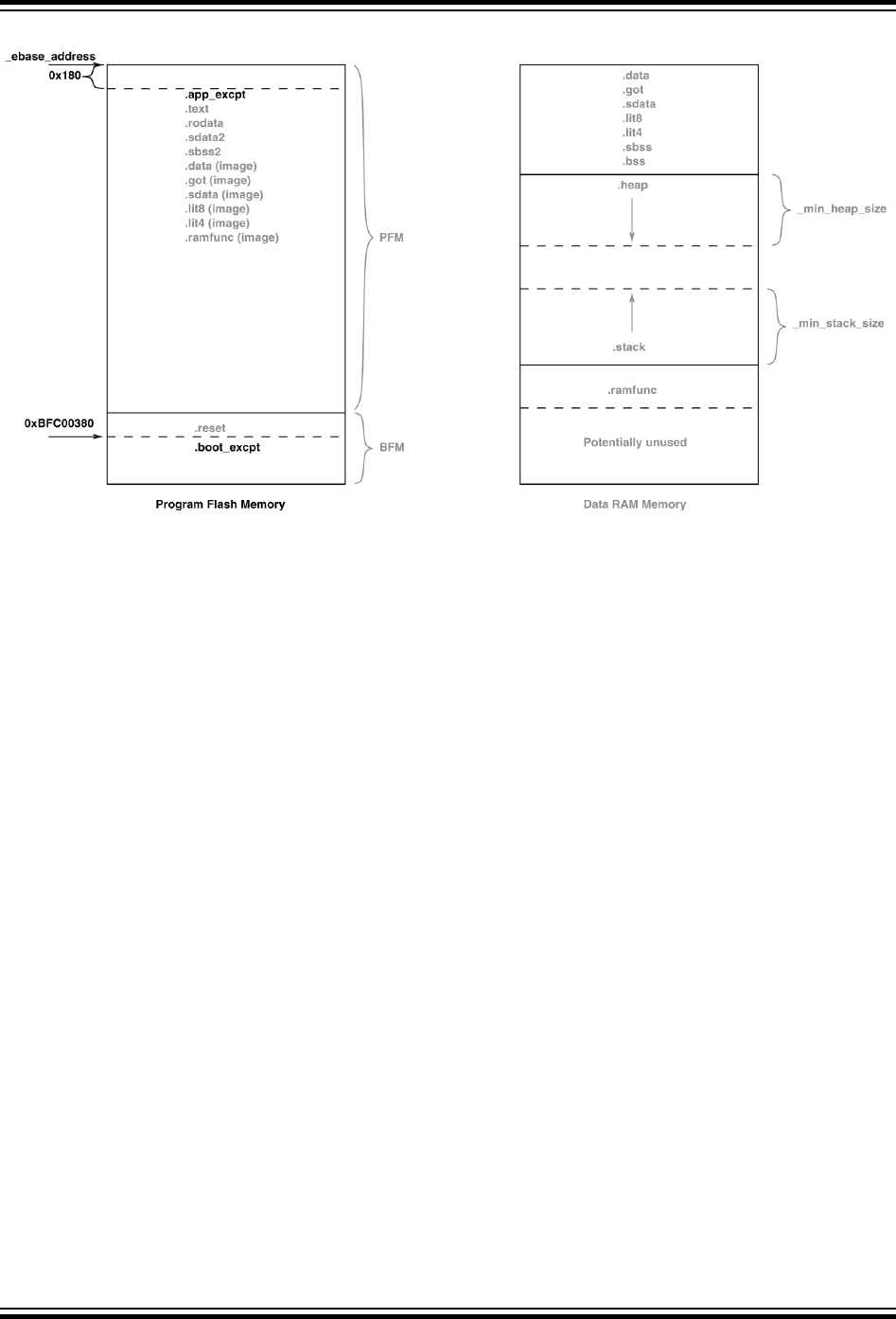
Figure 16-4. Exceptions
16.3 The On Reset Routine
Some hardware configurations require special initialization, often within the first few instruction cycles after Reset. To
achieve this, there is a hook provided via the on Reset routine.
This routine is called after initializing a minimum ‘C’ context. An empty weak version of this procedure (_on_reset)
is provided with the start-up code. A stub for this routine can be found in pic32m-libs/libpic32/stubs in the
installation directory of your compiler.
Special consideration needs to be taken by the user if this procedure is written in ‘C’. Most importantly, statically
allocated variables are not initialized (with either the specified initializer or a zero as required for uninitialized
variables). The stack pointer has been initialized when this routine is called.
16.3.1 Clearing Objects
The runtime start-up code will clear all memory locations occupied by uninitialized variables so they will contain zero
before main() is executed.
Variables whose contents should be preserved over a Reset should use the persistent attribute, see 9.9
Standard Type Qualifiers for more information. Such variables are linked in a different area of memory and are not
altered by the runtime start-up code in any way.
XC32 Compiler for PIC32M
Main, Runtime Start-up and Reset
© 2020 Microchip Technology Inc.
User Guide
DS50002799B-page 180

17. Library Routines
17.1 Using Library Routines
Library functions or routines (and any associated variables) will be automatically linked into a program once they
have been referenced in your source code. The use of a function from one library file will not include any other
functions from that library. Only used library functions will be linked into the program output and consume memory.
Your program will require declarations for any functions or symbols used from libraries. These are contained in the
standard C header (.h) files. Header files are not library files and the two files types should not be confused. Library
files contain precompiled code, typically functions and variable definitions; the header files provide declarations (as
opposed to definitions) for functions, variables and types in the library files, as well as other preprocessor macros.
#include <math.h> // declare function prototype for sqrt
int main(void)
{
double i;
// sqrt referenced; sqrt will be linked in from library file
i = sqrt(23.5);
}
A comprehensive and readily accessible set of peripheral libraries, drivers, and system services is available from
MPLAB
®
Harmony. Please see www.microchip.com/mplab/mplab-harmony for details.
XC32 Compiler for PIC32M
Library Routines
© 2020 Microchip Technology Inc.
User Guide
DS50002799B-page 181

18. Mixing C/C++ and Assembly Language
Assembly language code can be mixed with C/C++ code using two different techniques: writing assembly code and
placing it into a separate assembler module, or including it as in-line assembly in a C/C++ module. This section
describes how to use assembly language and C/C++ modules together. It gives examples of using C/C++ variables
and functions in assembly code, and examples of using assembly language variables and functions in C/C++.
The more assembly code a project contains, the more difficult and time consuming its maintenance will be. As the
project is developed, the compiler may work in different ways as some optimizations look at the entire program. The
assembly code is more likely to fail if the compiler is updated due to differences in the way the updated compiler may
work. These factors do not affect code written in C/C++.
Note: If assembly must be added, it is preferable to write this as self-contained routine in a separate assembly
module rather than in-lining it in C code.
18.1 Mixing Assembly Language and C Variables and Functions
The following guidelines indicate how to interface separate assembly language modules with C modules.
• Follow the register conventions described in 13.2 Register Conventions. In particular, registers $4-$7 are used
for parameter passing. An assembly -language function will receive parameters, and should pass arguments to
called functions, in these registers.
• Table 13-1 describes which registers must be saved across non-interrupt function calls.
• Interrupt functions must preserve all registers. Unlike a normal function call, an interrupt may occur at any point
during the execution of a program. When returning to the normal program, all registers must be as they were
before the interrupt occurred.
• Variables or functions declared within a separate assembly file that will be referenced by any C source file
should be declared as global using the assembler directive .global. Undeclared symbols used in assembly
files will be treated as externally defined.
The following example shows how to use variables and functions in both assembly language and C regardless of
where they were originally defined.
The file ex1.c defines foo and cVariable to be used in the assembly language file. The C file also shows how to
call an assembly function, asmFunction, and how to access the assembly defined variable, asmVariable.
Example 18-1. Mixing C and Assembly
/*
** file: ex1.S
*/
#include <xc.h>
/* define which section (for example "text")
* does this portion of code resides in. Typically,
* all your code will reside in .text section as
* shown below.
*/
.text
/* This is important for an assembly programmer. This
* directive tells the assembler that don't optimize
* the order of the instructions as well as don't insert
* 'nop' instructions after jumps and branches.
*/
.set noreorder
/*********************************************************************
* asmFunction(int bits)
* This function clears the specified bites in IOPORT A.
********************************************************************/
.global asmFunction
.ent asmFunction
asmFunction:
/* function prologue - save registers used in this function
XC32 Compiler for PIC32M
Mixing C/C++ and Assembly Language
© 2020 Microchip Technology Inc.
User Guide
DS50002799B-page 182

* on stack and adjust stack-pointer
*/
addiu sp, sp, -4
sw s0, 0(sp)
la s0, LATACLR
sw a0, 0(s0) /* clear specified bits */
la s0, PORTA
lw s1, 0(s0)
la s0, cVariable
sw s1, 0(s0) /* keep a copy */
/* function epilogue - restore registers used in this function
* from stack and adjust stack-pointer
*/
lw s0, 0(sp)
addiu sp, sp,
addu s1, ra, zero
jal foo
nop
addu ra, s1, zero
nop
/* return to caller */
jr ra
nop
.end asmFunction
.bss
.global asmVariable
.align 2
asmVariable: .space 4
The file ex1.S defines asmFunction and asmVariable as required for use in a linked
application. The assembly file also shows how to call a C function, foo, and how to access a C
defined variable, cVariable.
/*
* file: ex2.c
*/
#include <xc.h>
extern void asmFunction(int bits);
extern unsigned int asmVariable;
volatile unsigned int cVariable = 0;
volatile unsigned int jak = 0;
int
main(void) {
TRISA = 0;
LATA = 0xC6FFul;
asmFunction(0xA55Au);
while (1) {
asmVariable++;
}
}
void
foo(void) {
jak++;
}
In the C file, ex2.c, external references to symbols declared in an assembly file are declared using
the standard extern keyword; note that asmFunction is a void function and is declared
accordingly.
In the assembly file, ex1.S, the symbols asmFunction and asmVariable are made globally
visible through the use of the .global assembler directive and can be accessed by any other
source file.
XC32 Compiler for PIC32M
Mixing C/C++ and Assembly Language
© 2020 Microchip Technology Inc.
User Guide
DS50002799B-page 183
18.2 Using Inline Assembly Language
Within a C/C++ function, the asm statement may be used to insert a line of assembly-language code into the
assembly language that the compiler generates. Inline -assembly has two forms: simple and extended.
In the simple form, the assembler instruction is written using the syntax:
asm ("instruction");
where instruction is a valid assembly-language construct. If you are writing inline assembly in ANSI C programs,
write _ _asm_ _ instead of asm.
Note: Only a single string can be passed to the simple form of inline assembly.
In an extended assembler instruction using asm, the operands of the instruction are specified using C/C++
expressions. The extended syntax is:
asm("template" [ : [ "constraint"(output-operand) [ , ... ] ]
[ : [ "constraint"(input-operand) [ , ... ] ]
[ "clobber" [ , ... ] ]
]
]);
You must specify an assembler instruction template, plus an operand constraint string for each operand. The
template specifies the instruction mnemonic, and optionally placeholders for the operands. The constraint
strings specify operand constraints, for example, that an operand must be in a register (the usual case), or that an
operand must be an immediate value.
Constraint letters and modifiers supported by the compiler are listed in the following tables.
Table 18-1. Register Constraint Letters Supported by the Compiler
Letter Constraint
c
A register suitable for use in an indirect jump
d
An address register. This is equivalent to @code{r} unless generating
MIPS16 code
ka
Registers that can be used as the target of multiply-accumulate
instructions
l
The @code{lo} register. Use this register to store values that are no
bigger than a word
x
The concatenated @code{hi} and @code{lo} registers. Use this
register to store double-word values
Table 18-2. Integer Constraint Letters Supported by the Compiler
Letter Constraint
I
A signed 32-bit constant (for arithmetic instructions)
J
Integer zero
K
An unsigned 32-bit constant (for logic instructions)
L
A signed 32-bit constant in which the lower 32 bits are zero. Such
constants can be loaded using @code{lui}
M
A constant that cannot be loaded using @code{lui}, @code{addiu} or
@code{ori}
N
A constant in the range -65535 to -1 (inclusive)
O
A signed 15-bit constant
XC32 Compiler for PIC32M
Mixing C/C++ and Assembly Language
© 2020 Microchip Technology Inc.
User Guide
DS50002799B-page 184
...........continued
Letter Constraint
P
A constant in the range 1 to 65535 (inclusive)
Table 18-3. General Constraint Letters Supported by the Compiler
Letter Constraint
R
An address that can be used in a non-macro load or store.
Table 18-4. Constraint Modifiers Supported by the Compiler
Letter Constraint
=
Means that this operand is write-only for this instruction: the previous
value is discarded and replaced by output data
+
Means that this operand is both read and written by the instruction
&
Means that this operand is an earlyclobber operand, which is
modified before the instruction is finished using the input operands.
Therefore, this operand may not lie in a register that is used as an
input operand or as part of any memory address
d
Second register for operand number n, that is, %dn..
q
Fourth register for operand number n, that is, %qn..
t
Third register for operand number n, that is, %tn..
18.2.1 Inline Examples
Insert Bit Field
This example demonstrates how to use the INS instruction to insert a bit field into a 32-bit wide variable. This
function-like macro uses inline assembly to emit the INS instruction, which is not commonly generated from C/C++
code.
/* MIPS32r2 insert bits */
#define _ins(tgt,val,pos,sz) __extension__({ \
unsigned int __t = (tgt), __v = (val); \
__asm__ ("ins %0,%z1,%2,%3" /* template */ \
: "+d" (__t) /* output */ \
: "dJ" (__v), "I" (pos), "I" (sz)); /* input */ \
__t; \
})
Here__v, pos, and sz are input operands. The __v operand is constrained to be of type 'd' (an address register) or
'J' (integer zero). The pos and sz operands are constrained to be of type 'I' (a signed 32-bit constant).
The __t output operand is constrained to be of type 'd' (an address register). The '+' modifier means that this
operand is both read and written by the instruction and so the operand is both an input and an output.
The following example shows this macro in use.
unsigned int result;
void example (void)
{
unsigned int insertval = 0x12;
result = 0xAAAAAAAAu;
result = _ins(result, insertval, 4, 8);
/* result is now 0xAAAAA12A */
}
XC32 Compiler for PIC32M
Mixing C/C++ and Assembly Language
© 2020 Microchip Technology Inc.
User Guide
DS50002799B-page 185

For this example, the compiler may generate assembly code similar to the following.
li $2,-1431699456 # 0xaaaa0000
ori $2,$2,0xaaaa # 0xaaaa0000 | 0xaaaa
li $3,18 # 0x12
ins $2,$3,4,8 # inline assembly
lui $3,%hi(result) # assign the result back
j $31 # return
sw $2,%lo(result)($3)
Multiple Assembler Instructions
This example demonstrates how to use the WSBH and ROTR instructions together for a byte swap. The WSBH
instruction is a 32-bit byte swap within each of the two halfwords. The ROTR instruction is a rotate right by immediate.
This function-like macro uses inline assembly to create a “byte-swap word” using instructions that are not commonly
generated from C/C++ code.
The following shows the definition of the function-like macro, _bswapw.
/* MIPS32r2 byte-swap word */
#define _bswapw(x) __extension__({ \
unsigned int __x = (x), __v; \
__asm__ ("wsbh %0,%1;\n\t" \
"rotr %0,16" /* template */ \
: "=d" (__v) /* output */ \
: "d" (__x)) /* input*/ ; \
__v; \
})
Here __x is the C expression for the input operand. The operand is constrained to be of type 'd', which denotes an
address register.
The C expression __v is the output operand. This operand is also constrained to be of type 'd'. The '=' means that
this operand is write-only for this instruction: the previous value is discarded and replaced by output data.
The function-like macro is shown in the following example assigning to result the content of value, swapped.
unsigned int result;
int example (void)
{
unsigned int value = 0x12345678u;
result = _bswapw(value);
/* result == 0x78563412 */
}
The compiler may generate assembly code similar to the following for this example:
li $2,305397760 # 0x12340000
addiu $2,$2,22136 # 0x12340000 + 0x5678
wsbh $2,$2 # From inline asm
rotr $2,16 # From inline asm
lui $2,%hi(result) # assign back to result
j $31 # return
sw $3,%lo(result)($2)
18.2.2 Equivalent Assembly Symbols
C/C++ symbols can be accessed directly with no modification in extended assembly code.
18.3 Predefined Macros
Several predefined macros are available once you include <xc.h>. The exact operation of these macros is dependent
on the instruction set employed. The following table shows general purpose predefined macros and their operation.
XC32 Compiler for PIC32M
Mixing C/C++ and Assembly Language
© 2020 Microchip Technology Inc.
User Guide
DS50002799B-page 186
Table 18-5. Predefined Macros in XC.H
Macro Description
_bcc0(rn, sel, clr)
For the CP0 register specified by rn and sel, clear bits
corresponding to those bits in clr which are non-zero.
_bcsc0(rn, sel, clr, set)
For the CP0 register specified by rn and sel, clear bits
corresponding to those bits in clr which are non-zero, and set bits
corresponding to those bits in set which are non-zero.
_bsc0(rn, sel, set)
For the CP0 register specified by rn and sel, clear bits
corresponding to those bits in clr which are non-zero.
_bswapw(x)
See <xc.h> file. Byte-swap word.
_cache(op,addr)
Do an operation to a cache line. See the device documentation for
details on the available operations.
_clo(x)
Count leading ones in x.
_clz(x)
Count leading zeros in x.
_ctz(x)
Count trailing zeros in x.
_dclo(x)
Simulate 64-bit count leading ones in x.
_dclz(x)
Simulate 64-bit count leading zeros in x.
_dctz(x
Simulate 64-bit count trailing zeros in x.
_ehb()
Insert Execution Hazard Barrier instruction.
_ext(x,pos,sz)
See <xc.h> file. Extract bitfield from a 32-bit variable.
_get_byte(addr, errp)
Return the least significant byte of addr.
_get_dword(addr, errp)
Return the least significant 64-bit word of addr.
_get_half(addr, errp)
Return the least significant 16-bit word of addr.
_get_word(addr, errp)
Return the least significant 32-bit word of addr.
_ins(tgt,val,pos,sz)
See <xc.h> file. Insert bits.
_jr_hb()
See <xc.h> file. Jump register with hazard barrier.
_mfc0(rn, sel)
See <xc.h> file. Move a value from a coprocessor 0 register.
_mtc0(rn, sel, v)
See <xc.h> file. Move a value to a coprocessor 0 register.
_mxc0(rn, sel, v)
See <xc.h> file. Exchange a value with a value in a coprocessor 0
register.
_nop()
Insert a No Operation instruction.
_prefetch(hint,x)
Prefetch instruction for memory reference optimization. An
application that knows in advance it may need data can arrange for
it to be brought into cache. 'hint' defines which sort of prefetch this
is.
_put_byte(addr, v)
Write the least significant byte of addr with v.
_put_dword(addr, v)
Write the least significant 64-bit word of addr with v.
_put_half(addr, v)
Write the least significant 16-bit word of addr with v.
_put_word(addr, v)
Write the least significant 32-bit word of addr with v.
XC32 Compiler for PIC32M
Mixing C/C++ and Assembly Language
© 2020 Microchip Technology Inc.
User Guide
DS50002799B-page 187

...........continued
Macro Description
_rdpgpr(regno)
See <xc.h> file. Read register from previous register set.
_sync()
Insert Synchronize Shared Memory instruction.
_synci(addr)
Synchronize the I-cache with the D-cache; Run instruction for each
cache-line-sized block after writing instructions but before executing
them.
_wait()
Insert instruction to enter Standby mode.
_wrpgpr(regno, val)
See <xc.h> file. Write to a register in the previous register set.
_wsbh(x)
See <xc.h> file. 32-bit byte-swap within each of the two halfword.
__XC32_PART_SUPPORT_UPDATE
This macro expands to the letter corresponding to the part-support
update version being used. The value is based upon the major and
minor version numbers of the current release. For example, part-
support update version v1.42(B) will have #define
__XC32_PART_SUPPORT_UPDATE B
__XC32_PART_SUPPORT_VERSION
This macro expands to a numeric value corresponding to the part-
support update version being used. The value is based upon the
major and minor version numbers of the current release. For
example, part-support update version v1.42(B) will have #define
__XC32_PART_SUPPORT_UPDATE 1420.
XC32 Compiler for PIC32M
Mixing C/C++ and Assembly Language
© 2020 Microchip Technology Inc.
User Guide
DS50002799B-page 188

19. Optimizations
Different MPLAB XC32 C/C++ Compiler editions support different levels of optimization. Some editions are free to
download and others must be purchased. Visit https://www.microchip.com/mplab/compilers for more information on C
and C++ licenses.
The compiler editions are:
Edition Cost Description
Professional (PRO) Yes Implemented with the highest optimizations and
performance levels.
Free No Implemented with the most code optimizations
restrictions.
Evaluation (EVAL) No PRO edition enabled for 60 days and then reverts to
Free edition.
Setting Optimization Levels
Different optimizations may be set ranging from no optimization to full optimization, depending on your compiler
edition. When debugging code, you may wish to not optimize your code to ensure expected program flow.
For details on compiler options used to set optimizations, see 6.7.7 Options for Controlling Optimization.
XC32 Compiler for PIC32M
Optimizations
© 2020 Microchip Technology Inc.
User Guide
DS50002799B-page 189

20. Preprocessing
All C/C++ source files are preprocessed before compilation. Assembly source files that use the .S extension (upper
case) are also preprocessed. A large number of options control the operation of the preprocessor and preprocessed
code, see 6.7.8 Options for Controlling the Preprocessor.
20.1 C/C++ Language Comments
A C/C++ comment is ignored by the compiler and can be used to provide information to someone reading the source
code. They should be used freely.
Comments may be added by enclosing the desired characters within /* and */. The comment can run over multiple
lines, but comments cannot be nested. Comments can be placed anywhere in C/C++ code, even in the middle of
expressions, but cannot be placed in character constants or string literals.
Since comments cannot be nested, it may be desirable to use the #if preprocessor directive to comment out code
that already contains comments, for example:
#if 0
result = read(); /* TODO: Jim, check this function is right */
#endif
Single-line, C++ style comments may also be specified. Any characters following // to the end of the line are taken to
be a comment and will be ignored by the compiler, as shown below:
result = read(); // TODO: Jim, check this function is right
20.2 Preprocessor Directives
MPLAB XC32 C/C++ Compiler accepts all the standard preprocessor directives, which are listed in the following
table.
Table 20-1. Preprocessor Directives
Directive Meaning Example
#
Preprocessor null directive, do
nothing.
#
#assert
Generate error if condition false.
#assert SIZE > 10
#define
Define preprocessor macro.
#define SIZE 5
#define FLAG
#define add(a,b) ((a)+(b))
#elif
Short for #else #if.
see #ifdef
#else
Conditionally include source lines.
see #if
#endif
Terminate conditional source
inclusion.
see #if
#error
Generate an error message.
#error Size too big
#if
Include source lines if constant
expression true.
#if SIZE < 10
c = process(10)
#else
skip();
#endif
XC32 Compiler for PIC32M
Preprocessing
© 2020 Microchip Technology Inc.
User Guide
DS50002799B-page 190
...........continued
Directive Meaning Example
#ifdef
Include source lines if preprocessor
symbol defined.
#ifdef FLAG
do_loop();
#elif SIZE == 5
skip_loop();
#endif
#ifndef
Include source lines if preprocessor
symbol not defined.
#ifndef FLAG
jump();
#endif
#include
Include text file into source.
#include <stdio.h>
#include "project.h"
#line
Specify line number and file name for
listing.
#line 3 final
#nn (Where nn is a number) short for
#line nn.
#20
#pragma
Compiler specific options. Refer to 20.3 Pragma Directives
#undef
Undefines preprocessor symbol.
#undef FLAG
#warning
Generate a warning message.
#warning Length not set
Macro expansion using arguments can use the # character to convert an argument to a string, and the ## sequence
to concatenate arguments. If two expressions are being concatenated, consider using two macros in case either
expression requires substitution itself, so for example,
#define paste1(a,b) a##b
#define paste(a,b) paste1(a,b)
lets you use the paste macro to concatenate two expressions that themselves may require further expansion. The
replacement token is rescanned for more macro identifiers, but remember that once a particular macro identifier has
been expanded, it will not be expanded again if it appears after concatenation.
The type and conversion of numeric values in the preprocessor domain is the same as in the C domain.
Preprocessor values do not have a type, but acquire one as soon as they are converted by the preprocessor.
Expressions may overflow their allocated type in the same way that C expressions may overflow.
Overflow may be avoided by using a constant suffix. For example, an L after the number indicates it should be
interpreted as a long once converted.
So, for example:
#define MAX 100000*100000
and
#define MAX 100000*100000L
(note the L suffix) will define the values 0x540be400 and 0x2540be400, respectively.
20.3 Pragma Directives
There are certain compile-time directives that can be used to modify the behavior of the compiler. These are
implemented through the use of the ANSI standard #pragma facility. Any pragma which is not understood by the
compiler will be ignored.
XC32 Compiler for PIC32M
Preprocessing
© 2020 Microchip Technology Inc.
User Guide
DS50002799B-page 191

The format of a pragma is:
#pragma keyword options
where keyword is one of a set of keywords, some of which are followed by certain options. A description of the
keywords is given below.
#pragma interrupt
Mark a function as an interrupt handler. The prologue and epilogue code for the function will perform more extensive
context preservation. Note that the interrupt attribute (rather than this pragma) is the recommended mechanism
for marking a function as an interrupt handler. The interrupt pragma is provided for compatibility with other compilers.
See 15. Interrupts and 15.4 Exception Handlers.
#pragma vector
Generate a branch instruction at the indicated exception vector that targets the function. Note that the vector
attribute (rather than this pragma) is the recommended mechanism for generating an exception/interrupt vector. See
15. Interrupts and 15.4 Exception Handlers.
#pragma config
The #pragma config directive specifies the processor-specific configuration settings (that is, Configuration bits) to
be used by the application. See 8.4 Configuration Bit Access.
20.4 Predefined Macros
These predefined macros are available for use with the compiler.
20.4.1 32-Bit C/C++ Compiler Macros
The compiler defines a number of macros, most with the prefix “_MCHP_”, which characterize the various target
specific options, the target processor and other aspects of the host environment.
_MCHP_SZINT
32 or 64, depending on command line options to set the size of an
integer (-mint32 -mint64).
_MCHP_SZLONG
32 or 64, depending on command line options to set the size of an
integer (-mlong32 -mlong64).
_MCHP_SZPTR
32 always since all pointers are 32 bits.
__mchp_no_float
Defined if -mno-float specified.
__NO_FLOAT
Defined if -mno-float specified.
__SOFT_FLOAT
Defined if -mno-float not specified and the specified device does not
feature a hardware Floating-Point Unit (FPU). Indicates that floating-
point operations are supported via library calls.
__HARD_FLOAT
Defined if -mno-float and -msoft-float are not specified and the
specified device features a hardware Floating-Point Unit (FPU).
Indicates that floating-point operations utilize the FPU.
__PIC__
__pic__
The translation unit is being compiled for position independent code.
__PIC32MX
__PIC32MX__
Defined when a PIC32MX device is specified with the -mprocessor
option.
__PIC32MZ
Defined when a PIC32MZ device is specified with the -mprocessor
option.
XC32 Compiler for PIC32M
Preprocessing
© 2020 Microchip Technology Inc.
User Guide
DS50002799B-page 192

__PIC32_FEATURE_SET__
The compiler predefines a macro based on the features available for the
selected device. These macros are intended to be used when writing
code to take advantage of features available on newer devices while
maintaining compatibility with older devices.
Examples: PIC32MX795F512L would use: __PIC32_FEATURE_SET__
== 795, and PIC32MX340F128H would use:
__PIC32_FEATURE_SET__ == 340.
Examples: PIC32MZ2048ECH100 would use:
__PIC32_FEATURE_SET "EC" /* PIC32MZ2048ECH100 */
__PIC32_FEATURE_SET0 69 /* PIC32MZ2048ECH100 */
__PIC32_FEATURE_SET1 67 /* PIC32MZ2048ECH100 */
PIC32MX
Defined if -ansi is not specified.
__LANGUAGE_ASSEMBLY
__LANGUAGE_ASSEMBLY__
_LANGUAGE_ASSEMBLY
Defined if compiling a pre-processed assembly file (.S files).
LANGUAGE_ASSEMBLY
Defined if compiling a pre-processed assembly file (.S files) and -ansi
is not specified.
__LANGUAGE_C
__LANGUAGE_C__
_LANGUAGE_C
Defined if compiling a C file.
LANGUAGE_C
Defined if compiling a C file and -ansi is not specified.
__LANGUAGE_C_PLUS_PLUS
__cplusplus
_LANGUAGE_C_PLUS_PLUS__
Defined if compiling a C++ file.
__EXCEPTIONS
Defined if X++ exceptions are enabled.
__GXX_RTTI
Defined if runtime type information is enabled.
__processor__
Where “processor” is the capitalized argument to the -mprocessor
option. for example, -mprocessor=32mx12f3456 will define
__32MX12F3456__
__XC
Always defined to indicate that this is a Microchip XC compiler.
__XC32
Always defined to indicate this the XC32 compiler.
__VERSION__
The __VERSION__ macro expands to a string constant describing the
compiler in use. Do not rely on its contents having any particular form,
but it should contain at least the release number. Use the
__XC32_VERSION macro for a numeric version number.
__XC32_VERSION
or __C32_VERSION__
The C compiler defines the constant __XC32_VERSION, giving a
numeric value to the version identifier. This macro can be used to
construct applications that take advantage of new compiler features
while still remaining backward compatible with older versions. The value
is based upon the major and minor version numbers of the current
release. For example, release version 1.03 will have a
__XC32_VERSION definition of 1030. This macro can be used, in
conjunction with standard preprocessor comparison statements, to
conditionally include/exclude various code constructs.
XC32 Compiler for PIC32M
Preprocessing
© 2020 Microchip Technology Inc.
User Guide
DS50002799B-page 193

__mips_dsp 1
__mips_dspr2 1
__mips_dsp_rev 2
The C compiler defines these constants when the selected target device
supports the DSPr2 engine.
__mips_micromips 1
The compiler defines these constants when we are building for the
microMIPS compressed ISA as the default using the -mmicromips
option.
__mips_soft_float 1
The compiler defines this constant when we are compiling for software
floating-point operations.
See also the device-specific include files (pic32mx/include/proc/p32*.h) for other macros that can be used to
determine the features available on the selected device. You will find these macros near the end of the header file.
20.4.2 SDE Compatibility Macros
The MIPS
®
SDE (Software Development Environment) defines a number of macros, most with the prefix “_MIPS_”,
which characterize various target specific options, some determined by command line options (for example, -
mint64). Where applicable, these macros will be defined by the compiler in order to ease porting applications and
middleware from the SDE to the compiler.
_MIPS_SZINT
_MIPS_SZLONG
_MIPS_SZPTR
__mips_no_float
__mips__
_mips
_MIPS_ARCH_PIC32MX
_MIPS_TUNE_PIC32MX
_R3000
__R3000
__R3000__
__mips_soft_float
__MIPSEL
__MIPSEL__
_MIPSEL
Always defined.
R3000
MIPSEL
Defined if -ansi is not specified.
_mips_fpr
Defined as 32.
__mips16
Defined if -mips16 specified.
__mips
Defined as 32.
__mips_isa_rev
Defined as 2.
_MIPS_ISA
Defined as _MIPS_ISA_MIPS32.
20.4.3 Processor-Specific Macros
The proc/p*.h header files define a number of processor-specific macros. To use these macros, #include <xc.h>
in your source file. This list is not comprehensive.
XC32 Compiler for PIC32M
Preprocessing
© 2020 Microchip Technology Inc.
User Guide
DS50002799B-page 194

__PIC32_HAS_L1CACHE
Defined if and only if the target device supports an L1 cache
__PIC32_HAS_MIPS32R2
Defined if and only if the target device supports the MIPS32r2
Instruction Set
__PIC32_HAS_MICROMIPS
Defined if and only if the target device supports the
microMIPS32 Instruction Set
__PIC32_HAS_MIPS16
Defined if and only if the target device supports the MIPS16
Instruction Set
__PIC32_HAS_DSPR2
Defined if and only if the target device supports the DSP-
enhanced core
__PIC32_HAS_FPU64
Defined if and only if the target device supports the 64-bit
Hardware Floating-Point Unit. Also check
__mips_hard_float to determine if the compiler is set to
compile for the FPU.
_<Interrupt-Source>_VECTOR
Defined to the vector number for the interrupt source and
intended to be used with the vector function attribute. for
example, #define _CORE_TIMER_VECTOR 0
_<Interrupt-Source>_IRQ
Defined to the IRQ number for the interrupt source. for
example, #define _CORE_SOFTWARE_0_IRQ 1
_<SFR>_<Bitfield>_POSITION
Defined to the position of a bitfield within a special function
register (SFR). for example, #define
_WDTCON_ON_POSITION 0x0000000F
_<SFR>_<Bitfield>_MASK
Defined to a mask of the bitfield within a special function
register (SFR). for example, #define _WDTCON_ON_MASK
0x00008000
_<SFR>_<Bitfield>_LENGTH
Defined to the length of the bitfield within a special function
register (SFR). for example, #define
_WDTCON_ON_LENGTH 0x00000001
<Special-Function-Register>
Defined to the Special Function Register name. for example,
#define T5CON T5CON
This macro allows preprocessor testing for the existence of
an SFR before using it. For example:
#if defined(T5CON)
T5CONbits.ON = 1;
#endif
XC32 Compiler for PIC32M
Preprocessing
© 2020 Microchip Technology Inc.
User Guide
DS50002799B-page 195

21. Linking Programs
See the MPLAB
®
XC32 Assembler, Linker and Utilities User’s Guide (DS50002186) for more detailed information on
the linker.
The compiler will automatically invoke the linker unless the compiler has been requested to stop after producing an
intermediate file.
Linker scripts are used to specify the available memory regions and where sections should be positioned in those
regions.
The linker creates a map file which details the memory assigned to sections. The map file is the best place to look for
memory information.
21.1 Replacing Library Symbols
Unlike with the Microchip MPLAB XC8 compiler, not all library functions can be replaced with user-defined routines
using MPLAB XC32 C/C++ Compiler. Only weak library functions (see ) can be replaced in this way. For those that
are weak, any function you write in your code will replace an identically named function in the library files.
21.2 Linker-Defined Symbols
The 32-bit linker defines several symbols that can be used in your C code development. Please see the MPLAB
®
XC32 Assembler, Linker and Utilities User’s Guide (DS50002186) for more information.
The linker defines the symbols _ramfunc_begin and _bmxdkpba_address, which represent the starting address
in RAM where ram functions will be accessed, and the corresponding address in the program memory from which the
functions will be copied. They are used by the default runtime start-up code to initialize the bus matrix if ram functions
exist in the project, see 14.3 Allocation of Function Code.
The linker also defines the symbol _stack, which is used by the runtime start-up code to initialize the stack pointer.
This symbol represents the starting address for the software stack.
All the above symbols are rarely required for most programs, but may assist you if you are writing your own runtime
start-up code.
21.3 Default Linker Script
For PIC32MX Devices Only:
If no linker script is specified on the command line, the linker will use an internal version known as the built-in default
linker script. The default linker script has section mapping that is appropriate for all PIC32 MCUs. It uses an
INCLUDE directive to include the device-specific memory regions.
The default linker script is appropriate for most PIC32 MCU applications. Only applications with specific memory-
allocation needs will require an application-specific linker script. The default linker script can be examined by invoking
the linker with the --verbose option:
xc32-ld --verbose
In a normal tool-suite installation, a copy of the default linker script is located at \pic32mx\lib\ldscripts
\elf32pic32mx.x. Note that this file is only a copy of the default linker script. The script that the linker uses is
internal to the linker.
The device-specific portion of the linker script is located in \pic32mx\pic32mx\lib\proc\32MXGENERIC
\procdefs.ld, where device is the device value specified to the -mprocessor compilation-driver (xc32-gcc)
option.
For PIC32MZ and Later Devices:
Single-file linker script for PIC32MZ and later devices: The linker script for PIC32MZ devices are contained within a
single file (for example, pic32mx/lib/proc/32MZ2048ECH100/p32MZ2048ECH100.ld). This eliminates the
XC32 Compiler for PIC32M
Linking Programs
© 2020 Microchip Technology Inc.
User Guide
DS50002799B-page 196

dependency on two files (elf32pic32mx.x and procdefs.ld) used by the older linker-script model. Like before,
the xc32-gcc compilation driver will pass the device-specific linker script to the linker when building with -
mprocessor=device option.
The default linker script contains the following categories of information:
• 21.3.1 Output Format and Entry Points
• 21.3.2 Default Values for Minimum Stack and Heap Sizes
• 21.3.3 Processor Definitions Include File for PIC32MX Family
– 21.3.3.1 Inclusion of Processor-Specific Object File(s)
– 21.3.3.2 Optional Inclusion of Processor-Specific Peripheral Libraries
– 21.3.3.3 Base Exception Vector Address and Vector Spacing Symbols
– 21.3.3.4 Memory Address Equates
– 21.3.3.5 Memory Regions
– 21.3.3.6 Configuration Words Input/Output Section Map
• 21.3.4 Input/Output Section Map
Note: All addresses specified in the linker scripts should be specified as virtual addresses, not physical addresses.
21.3.1 Output Format and Entry Points
The first several lines of the default linker script define the output format and the entry point for the application.
OUTPUT_FORMAT("elf32-tradlittlemips")
OUTPUT_ARCH(pic32mx)
ENTRY(_reset)
The OUTPUT_FORMAT line selects the object file format for the output file. The output object file format generated by
the 32-bit language tools is a traditional, little-endian, MIPS, ELF32 format.
The OUTPUT_ARCH line selects the specific machine architecture for the output file. The output files generated by the
32-bit language tools contain information that identifies the file was generated for the PIC32 architecture.
The ENTRY line selects the entry point of the application. This is the symbol identifying the location of the first
instruction to execute. The 32-bit language tools begins execution at the instruction identified by the _reset label.
21.3.2 Default Values for Minimum Stack and Heap Sizes
The next section of the default linker script provides default values for the minimum stack and heap sizes.
/*
* Provide for a minimum stack and heap size
* - _min_stack_size - represents the minimum space that must
* be made available for the stack. Can
* be overridden from the command line
* using the linker's --defsym option.
* - _min_heap_size - represents the minimum space that must
* be made available for the heap. Can
* be overridden from the command line
* using the linker's --defsym option.
*/
EXTERN (_min_stack_size _min_heap_size)
PROVIDE(_min_stack_size = 0x400) ;
PROVIDE(_min_heap_size = 0) ;
The EXTERN line ensures that the rest of the linker script has access to the default values of _min_stack_size and
_min_heap_size assuming that the user does not override these values using the linker’s --defsym command
line option.
The two PROVIDE lines ensure that a default value is provided for both _min_stack_size and _min_heap_size.
The default value for the minimum stack size is 1024 bytes (0x400). The default value for the minimum heap size is
0 bytes.
XC32 Compiler for PIC32M
Linking Programs
© 2020 Microchip Technology Inc.
User Guide
DS50002799B-page 197

21.3.3 Processor Definitions Include File for PIC32MX Family
The next line in the default linker script pulls in information specific to the processor.
INCLUDE procdefs.ld
The file procdefs.ld is included in the linker script at this point. The file is searched for in the current directory and
in any directory specified with the -L command line option. The compiler shell ensures that the correct directory is
passed to the linker with the -L command line option based on the processor selected with the -mprocessor
command line option.
The processor definitions linker script contains the following pieces of information:
• 21.3.3.1 Inclusion of Processor-Specific Object File(s)
• 21.3.3.3 Base Exception Vector Address and Vector Spacing Symbols
• 21.3.3.4 Memory Address Equates
• 21.3.3.5 Memory Regions
• 21.3.3.6 Configuration Words Input/Output Section Map
21.3.3.1 Inclusion of Processor-Specific Object File(s)
This section of the processor definitions linker script ensures that the processor-specific object file(s) get included in
the link.
/**************************************************************
* Processor-specific object file. Contains SFR
definitions.
**************************************************************/
INPUT("processor.o")
The INPUT line specifies that processor.o should be included in the link as if this file were named on the
command line. The linker attempts to find this file in the current directory. If it is not found, the linker searches through
the library search paths (that is, the paths specified with the -L command line option).
21.3.3.2 Optional Inclusion of Processor-Specific Peripheral Libraries
Note: The legacy peripheral libraries are deprecated and are replaced by the MPLAB Harmony libraries, installed
separately.
This section of the processor definitions linker script ensures that the processor-specific peripheral libraries get
included, but only if the files exist.
/*********************************************************************
* Processor-specific peripheral libraries are
optional
*********************************************************************/
OPTIONAL("libmchp_peripheral.a")
OPTIONAL("libmchp_peripheral_32MX795F512L.a")
The OPTIONAL lines specify that libmchp_peripheral.a and libmchp_peripheral_32MX795F512L.a
should be included in the link as if the files were named on the command line. The linker attempts to find these files in
the current directory. If they are not found in the current directory, the linker searches through the library search
paths. If they are not found in the library search paths, the link process continues without error. The linker will error
only when a symbol from the -peripheral library is required but not found elsewhere.
21.3.3.3 Base Exception Vector Address and Vector Spacing Symbols
This section of the processor definitions linker script defines values for the base exception vector address and vector
spacing.
/**************************************************************
XC32 Compiler for PIC32M
Linking Programs
© 2020 Microchip Technology Inc.
User Guide
DS50002799B-page 198
* For interrupt vector handling
**************************************************************/
_vector_spacing = 0x00000001;
_ebase_address = 0x9FC01000;
The first line defines a value of 1 for _vector_spacing. The available memory for exceptions only supports a
vector spacing of 1. The second line defines the location of the base exception vector address (EBASE).
On some devices, the base exception vector address is located in the KSEG0 boot segment. On other devices, the
size of the KSEG0 boot segment is not sufficient for the vector table, so the base exception vector address is located
in the KSEG0 program segment. In general, devices with at least 12 KB in the KSEG0 boot segment use the boot
flash for the exception vector table. Devices with less than 12 KB in the KSEG0 boot segment use the KSEG0
program segment for the exception vector table. Be sure to check the procdefs.ld include file for the default
address for your target device.
21.3.3.4 Memory Address Equates
This section of the processor definitions linker script provides information about certain memory addresses required
by the default linker script.
/**************************************************************
* Memory Address Equates
**************************************************************/
_RESET_ADDR =
0xBFC00000;
_BEV_EXCPT_ADDR =
0xBFC00380;
_DBG_EXCPT_ADDR =
0xBFC00480;
_DBG_CODE_ADDR =
0xBFC02000;
_GEN_EXCPT_ADDR =
_ebase_address + 0x180;
The _RESET_ADDR defines the processor’s Reset address. This is the virtual begin address of the IFM boot section
in Kernel mode.
The _BEV_EXCPT_ADDR defines the address that the processor jumps to when an exception is encountered and
Status
BEV
= 1.
The _DBG_EXCPT_ADDR defines the address that the processor jumps to when a debug exception is encountered.
The _DBG_CODE_ADDR defines the address that is the start address of the debug executive. Note that this address
may vary depending on the size of the KSEG0 boot segment on your target device.
The _GEN_EXCPT_ADDR defines the address that the processor jumps to when an exception is encountered and
Status
BEV
= 0.
21.3.3.5 Memory Regions
This section of the processor definitions linker script provides information about the memory regions that are
available on the device.
/**************************************************************
* Memory Regions
XC32 Compiler for PIC32M
Linking Programs
© 2020 Microchip Technology Inc.
User Guide
DS50002799B-page 199
*
* Memory regions without attributes cannot be
used for
* orphaned sections. Only sections specifically
assigned to
* these regions can be allocated into these
regions.
**************************************************************/
MEMORY
{
kseg0_program_mem (rx) : ORIGIN = 0x9D000000,
LENGTH = 0x8000
kseg0_boot_mem : ORIGIN = 0x9FC00490, LENGTH = 0x970
exception_mem : ORIGIN = 0x9FC01000, LENGTH = 0x1000
kseg1_boot_mem : ORIGIN = 0xBFC00000, LENGTH = 0x490
debug_exec_mem : ORIGIN = 0xBFC02000, LENGTH = 0xFF0
config3 : ORIGIN = 0xBFC02FF0, LENGTH =
0x4
config2 : ORIGIN = 0xBFC02FF4, LENGTH =
0x4
config1 : ORIGIN = 0xBFC02FF8, LENGTH =
0x4
config0 : ORIGIN = 0xBFC02FFC, LENGTH =
0x4
kseg1_data_mem : ORIGIN = 0xA0000000, LENGTH = 0x2000
sfrs : ORIGIN = 0xBF800000, LENGTH =
0x10000
}
Note: L1 cache devices use kseg1_data_mem.
Eleven memory regions are defined with an associated start address and length:
• Program memory region (kseg0_program_mem) for application code
• Boot memory regions (kseg0_boot_mem and kseg1_boot_mem)
• Exception memory region (exception_mem)
• Debug executive memory region (debug_exec_mem)
• Configuration memory regions (config3, config2, config1, and config0)
• Data memory region (kseg1_data_mem)
• SFR memory region (sfrs)
The default linker script uses these names to locate sections into the correct regions. Sections which are non-
standard become orphaned sections. The attributes of the memory regions are used to locate these orphaned
sections. The attributes (rx) specify that read-only sections or executable sections can be located into the program
XC32 Compiler for PIC32M
Linking Programs
© 2020 Microchip Technology Inc.
User Guide
DS50002799B-page 200

memory regions. Similarly, the attributes (w!x) specify that sections that are not read-only and not executable can be
located in the data memory region. Since no attributes are specified for the boot memory region, the configuration
memory regions, or the SFR memory region, only specified sections may be located in these regions (that is,
orphaned sections may not be located in the boot memory regions, the exception memory region, the configuration
memory regions, the debug executive memory region, or the SFR memory region).
21.3.3.6 Configuration Words Input/Output Section Map
The last section in the processor definitions linker script is the input/output section map for Configuration Words. This
section map is additive to the Input/Output Section Map found in the default linker script (see 21.3.4 Input/Output
Section Map). It defines how input sections for Configuration Words are mapped to output sections for Configuration
Words. Note that input sections are portions of an application that are defined in source code, while output sections
are created by the linker. Generally, several input sections may be combined into a single output section. All output
sections are specified within a SECTIONS command in the linker script.
For each Configuration Word that exists on the specific processor, a distinct output section
named .config_address exists where address is the location of the Configuration Word in memory. Each of these
sections contains the data created by the #pragma config directive (see 20.3 Pragma Directives) for that
Configuration Word. Each section is assigned to their respective memory region (con-fign).
SECTIONS
{
.config_BFC02FF0 : {
*(.config_BFC02FF0)
} > config3
.config_BFC02FF4 : {
*(.config_BFC02FF4)
} > config2
.config_BFC02FF8 : {
*(.config_BFC02FF8)
} > config1
.config_BFC02FFC : {
*(.config_BFC02FFC)
} > config0
}
21.3.4 Input/Output Section Map
The last section in the default linker script is the input/output section map. The section map is the heart of the linker
script. It defines how input sections are mapped to output sections. Note that input sections are portions of an
application that are defined in source code, while output sections are created by the linker. Generally, several input
sections may be combined into a single output section. All output sections are specified within a SECTIONS
command in the linker script.
21.3.4.1 .Config_<Address> Sections
These sections map the Configuration Words to their corresponding absolute addresses on the target device. The
compiler's config pragma generates the input sections using this naming convention, and the linker script then maps
the compiler-generated input section to the output section mapped to the corresponding absolute address.
21.3.4.2 .Reset Section
This section contains the code that is executed when the processor performs a Reset. This section is located at the
Reset address (_RESET_ADDR), as specified in the processor definitions linker script and is assigned to the boot
XC32 Compiler for PIC32M
Linking Programs
© 2020 Microchip Technology Inc.
User Guide
DS50002799B-page 201

memory region (kseg1_boot_mem). The .reset output section also contains the C start-up code from
the .reset.startup input section.
.reset _RESET_ADDR :
{
KEEP(*(.reset))
KEEP(*(.reset.startup))
} > kseg1_boot_mem
21.3.4.3 .bev_excpt Section
This section contains the handler for exceptions that occur when Status
BEV
= 1. This section is located at the BEV
exception address (_BEV_EXCPT_ADDR) as specified in the processor definitions linker script and is assigned to the
boot memory region (kseg1_boot_mem).
(kseg1_boot_mem).
.bev_excpt _BEV_EXCPT_ADDR :
{
(*(.bev_handler))
} > kseg1_boot_mem
21.3.4.4 .dbg_excpt Section
This section reserves space for the debug exception vector. This section is only allocated if the symbol _DEBUGGER
has been defined. (This symbol is defined if the -mde-bugger command line option is specified to the shell.) This
section is located at the debug exception address (_DBG_EXCPT_ADDR) as specified in the processor definitions
linker script and is assigned to the boot memory region (kseg1_boot_mem). The section is marked as NOLOAD as it
is only intended to ensure that application code cannot be placed at locations reserved for the debug executive.
.dbg_excpt _DBG_EXCPT_ADDR (NOLOAD) :
{
. += (DEFINED (_DEBUGGER) ? 0x8 : 0x0);
} > kseg1_boot_mem
21.3.4.5 .dbg_code Section
This section reserves space for the debug exception handler. This section is only allocated if the symbol _DEBUGGER
has been defined. (This symbol is defined if the -mde-bugger command line option is specified to the shell.) This
section is located at the debug code address (_DBG_CODE_ADDR) as specified in the processor definitions linker
script and is assigned to the debug executive memory region (debug_exec_mem). The section is marked as NOLOAD
because it is only intended to ensure that application code cannot be placed at locations reserved for the debug
executive.
.dbg_code _DBG_CODE_ADDR (NOLOAD) :
{
. += (DEFINED (_DEBUGGER) ? 0xFF0 : 0x0);
} > debug_exec_mem
21.3.4.6 .app_excpt Section
This section contains the handler for exceptions that occur when StatusBEV = 0. This section is located at the
general exception address (_GEN_EXCPT_ADDR) as specified in the processor definitions linker script and is
assigned to the exception memory region (exception_mem).
.app_excpt _GEN_EXCPT_ADDR :
{
KEEP(*(.gen_handler))
} > exception_mem
21.3.4.7 .vector_0 .. .vector_63 Sections (PIC32MX Interrupt Vector Tables)
PIC32MX devices use an Interrupt Vector Controller that provides 64 interrupt vectors with uniform, user-configurable
spacing.
For these devices, each vector in the table is created as an output section located at an absolute address based on
values of the _ebase_address and _vector_spacing symbols. There is one .vector_n output section for each
of the 64 vectors in the table.
XC32 Compiler for PIC32M
Linking Programs
© 2020 Microchip Technology Inc.
User Guide
DS50002799B-page 202

These sections contain the handler for each of the interrupt vectors. These sections are located at the correct
vectored addresses using the formula:
_ebase_address + 0x200 + (_vector_spacing << 5) * n
where n is the respective vector number.
Each of the sections is followed by an assert that ensures the code located at the vector does not exceed the vector
spacing specified.
.vector_n _ebase_address + 0x200 + (_vector_spacing << 5) * n :
{
KEEP(*(.vector_n))
} > exception_mem
ASSERT (SIZEOF(.vector_n) < (_vector_spacing << 5), "function at exception vector n too
large")
21.3.4.8 .vectors Section
Some PIC32 families feature variable offsets for vector spacing. This feature allows the interrupt vector spacing to be
configured according to application needs. A specific interrupt vector offset can be set for each vector using its
associated OFFxxx register. For details on the interrupt vector-table variable offset feature, refer to the “PIC32 -
Family Reference Manual” (DS61108) and also the data sheet for your specific PIC32 MCU.
The application source code is responsible for creating a .vector_n input section for each interrupt vector. The C/C
++ compiler creates this section when either the -vector(n) or the at_vector(n) attribute is applied to the
interrupt service routine. In assembly code, use the .section directive to create a new named section.
The device-specific linker script creates a single output section named .vectors that groups all of the
individual .vector_n input sections from the project. The start of the interrupt-vector table is mapped to the address
(_ebase_address + 0x200). The default value of the _ebase_address symbol is also provided in the linker
script.
For each vector, the linker script also creates a symbol named __vector_offset_n, whose value is the offset of
the vector address from the _ebase_address address.
PROVIDE(_ebase_address = 0x9D000000);
SECTIONS {
/* Interrupt vector table with vector offsets */
.vectors _ebase_address + 0x200 :
{
/* Symbol __vector_offset_n points to .vector_n if it exists,
* otherwise points to the default handler. The
* vector_offset_init.o module then provides a .data section
* containing values used to initialize the vector-offset SFRs
* in the crt0 startup code.
*/
__vector_offset_0 = (DEFINED(__vector_dispatch_0) ? (. - _ebase_address) :
__vector_offset_default); KEEP(*(.vector_0))
__vector_offset_1 = (DEFINED(__vector_dispatch_1) ? (. - _ebase_address) :
__vector_offset_default); KEEP(*(.vector_1))
__vector_offset_2 = (DEFINED(__vector_dispatch_2) ? (. - _ebase_address) :
__vector_offset_default); KEEP(*(.vector_2))
/* ... */
__vector_offset_190 = (DEFINED(__vector_dispatch_190) ? (. - _ebase_address) :
__vector_offset_default); KEEP(*(.vector_190))
}
}
The vector-offset initialization module (vector_offset_init.o) uses the __vector_offset_n symbols defined
in the default linker script. The value of each symbol is the offset of the vector’s address from the ebase register’s
address. The vector-offset initialization module, uses the symbol value to create a .data section using the address
of the corresponding OFFxxx special function register. This means that the standard linker-generated data-
initialization template contains the values used to initialize the OFFxxx registers.
With these .data sections added to the project and the linker-generated data-initialization template, the standard
runtime startup code initializes the OFFxxx special function registers as regular initialized data. No special code is
required in the startup code to initialize the OFFxxx registers.
XC32 Compiler for PIC32M
Linking Programs
© 2020 Microchip Technology Inc.
User Guide
DS50002799B-page 203

21.3.4.9 .text Section
The standard executable code sections are no longer mapped to the .text output section. However, a few special
executable sections are still mapped here as shown below. This section is assigned to the program memory region
(kseg0_program_mem) and has a fill value of NOP (0).
The built-in linker script no longer maps standard .text executable code input sections. By not mapping these
sections in the linker script, we allow these sections to be allocated using the best-fit allocator rather than the
sequential allocator. Sections that are unmapped in the linker script can flow around absolute sections specified in
code, whereas sections that are linker-script mapped are grouped together and allocated sequentially. This
potentially causes conflicts with absolute sections (using the address function attribute).
.text ORIGIN(kseg0_program_mem) :
{
*(.stub .gnu.linkonce.t.*)
KEEP (*(.text.*personality*))
*(.gnu.warning)
*(.mips16.fn.*)
*(.mips16.call.*)
} > kseg0_program_mem =0
21.3.4.10 C++ Initilization Sections
The sections .init, .preinit_array, .init_array, .fini_array, .ctors, and .dtors are all used for the
construction and destruction of file-scope static-storage C++ objects.
/* Global-namespace object initialization */
.init :
{
KEEP (*crti.o(.init))
KEEP (*crtbegin.o(.init))
KEEP (*(EXCLUDE_FILE (*crtend.o *crtend?.o *crtn.o ).init))
KEEP (*crtend.o(.init))
KEEP (*crtn.o(.init))
. = ALIGN(4) ;
} >kseg0_program_mem
.fini :
{
KEEP (*(.fini))
. = ALIGN(4) ;
} >kseg0_program_mem
.preinit_array :
{
PROVIDE_HIDDEN (__preinit_array_start = .);
KEEP (*(.preinit_array))
PROVIDE_HIDDEN (__preinit_array_end = .);
. = ALIGN(4) ;
} >kseg0_program_mem
.init_array :
{
PROVIDE_HIDDEN (__init_array_start = .);
KEEP (*(SORT(.init_array.*)))
KEEP (*(.init_array))
PROVIDE_HIDDEN (__init_array_end = .);
. = ALIGN(4) ;
} >kseg0_program_mem
.fini_array :
{
PROVIDE_HIDDEN (__fini_array_start = .);
KEEP (*(SORT(.fini_array.*)))
KEEP (*(.fini_array))
PROVIDE_HIDDEN (__fini_array_end = .);
. = ALIGN(4) ;
} >kseg0_program_mem
.ctors :
{
/* XC32 uses crtbegin.o to find the start of
the constructors, so we make sure it is
first. Because this is a wildcard, it
doesn't matter if the user does not
actually link against crtbegin.o; the
linker won't look for a file to match a
wildcard. The wildcard also means that it
XC32 Compiler for PIC32M
Linking Programs
© 2020 Microchip Technology Inc.
User Guide
DS50002799B-page 204

doesn't matter which directory crtbegin.o
is in. */
KEEP (*crtbegin.o(.ctors))
KEEP (*crtbegin?.o(.ctors))
/* We don't want to include the .ctor section from
the crtend.o file until after the sorted ctors.
The .ctor section from the crtend file contains the
end of ctors marker and it must be last */
KEEP (*(EXCLUDE_FILE (*crtend.o *crtend?.o ) .ctors))
KEEP (*(SORT(.ctors.*)))
KEEP (*(.ctors))
. = ALIGN(4) ;
} >kseg0_program_mem
.dtors :
{
KEEP (*crtbegin.o(.dtors))
KEEP (*crtbegin?.o(.dtors))
KEEP (*(EXCLUDE_FILE (*crtend.o *crtend?.o ) .dtors))
KEEP (*(SORT(.dtors.*)))
KEEP (*(.dtors))
. = ALIGN(4) ;
} >kseg0_program_mem
The order of the input sections within each output section is significant.
Note: The order of the input sections within each output section is significant.
21.3.4.11 .rodata Section
Standard read-only sections are not mapped in the linker script. A few special read-only sections are still mapped in
the linker script, but most sections are unmapped, allowing them to be handled by the best fit allocator. This section is
assigned to the program memory region (kseg0_program_mem).
.rodata :
{
*(.gnu.linkonce.r.*)
*(.rodata1)
} > kseg0_program_mem
21.3.4.12 .sdata2 Section
This section collects the small initialized constant global and static data from all of the application’s input files.
Because of the constant nature of the data, this section is also a read-only section. This section is assigned to the
program memory region (kseg0_program_mem).
/*
* Small initialized constant global and static data can be
* placed in the .sdata2 section. This is different from
* .sdata, which contains small initialized non-constant
* global and static data.
*/
.sdata2 :
{
*(.sdata2 .sdata2.* .gnu.linkonce.s2.*)
} > kseg0_program_mem
21.3.4.13 .sbss2 Section
This section collects the small uninitialized constant global and static data from all of the application’s input files.
Because of the constant nature of the data, this section is also a read-only section. This section is assigned to the
program memory region (kseg0_program_mem).
/*
* Uninitialized constant global and static data (that is,
* variables which will always be zero). Again, this is
* different from .sbss, which contains small non-initialized,
* non-constant global and static data.
*/
.sbss2 :
{
*(.sbss2 .sbss2.* .gnu.linkonce.sb2.*)
} > kseg0_program_mem
XC32 Compiler for PIC32M
Linking Programs
© 2020 Microchip Technology Inc.
User Guide
DS50002799B-page 205

21.3.4.14 .dbg_data Section
This section reserves space for the data required by the debug exception handler. This section is only allocated if the
symbol _DEBUGGER has been defined. (This symbol is defined if the -mdebugger command line option is specified
to the shell.) This section is assigned to the data memory region (kseg1_data_mem). The section is marked as
NOLOAD as it is only intended to ensure that application data cannot be placed at locations reserved for the debug
executive.
.dbg_data (NOLOAD) :
{
. += (DEFINED (_DEBUGGER) ? 0x200 : 0x0);
} > kseg1_data_mem
21.3.4.15 .data Section
The linker generates a data-initialization template that the C start-up code uses to initialize variables.
21.3.4.16 .got Section
This section collects the global offset table from all of the application’s input files. This section is assigned to the data
memory region (kseg1_data_mem) with a load address located in the program memory region
(kseg0_program_mem). A symbol is defined to represent the location of the Global Pointer (_gp).
_gp = ALIGN(16) + 0x7FF0 ;
.got :
{
*(.got.plt) *(.got)
} > kseg1_data_mem AT> kseg0_program_mem
21.3.4.17 .sdata Section
This section collects the small initialized data from all of the application’s input files. This section is assigned to the
data memory region (kseg1_data_mem) with a load address located in the program memory region
(kseg0_program_mem). Symbols are defined to represent the virtual begin (_sdata_begin) and end
(_sdata_end) addresses of this section.
/*
* We want the small data sections together, so
* single-instruction offsets can access them all, and
* initialized data all before uninitialized, so
* we can shorten the on-disk segment size.
*/
.sdata :
{
_sdata_begin = . ;
*(.sdata .sdata.* .gnu.linkonce.s.*)
_sdata_end = . ;
} > kseg1_data_mem AT> kseg0_program_mem
21.3.4.18 .lit8 Section
This section collects the 8-byte constants (usually floating-point) which the assembler decides to store in memory
rather than in the instruction stream from all of the application’s input files. This section is assigned to the data
memory region (kseg1_data_mem) with a load address located in the program memory region
(kseg0_program_mem).
.lit8 :
{
*(.lit8)
} > kseg1_data_mem AT> kseg0_program_mem
21.3.4.19 .lit4 Section
This section collects the 4-byte constants (usually floating-point) which the assembler decides to store in memory
rather than in the instruction stream from all of the application’s input files. This section is assigned to the data
memory region (kseg1_data_mem) with a load address located in the program memory region
XC32 Compiler for PIC32M
Linking Programs
© 2020 Microchip Technology Inc.
User Guide
DS50002799B-page 206

(kseg0_program_mem). A symbol is defined to represent the virtual end address of the initialized data
(_data_end).
.lit4 :
{
*(.lit4)
} > kseg1_data_mem AT> kseg0_program_mem
_data_end = . ;
21.3.4.20 .sbss Section
This section collects the small uninitialized data from all of the application’s input files. This section is assigned to the
data memory region (kseg1_data_mem). A symbol is defined to represent the virtual begin address of uninitialized
data (_bss_begin). Symbols are also defined to represent the virtual begin (_sbss_begin) and end (_sbss_end)
addresses of this section.
_bss_begin = . ;
.sbss :
{
_sbss_begin = . ;
*(.dynsbss)
*(.sbss .sbss.* .gnu.linkonce.sb.*)
*(.scommon)
_sbss_end = . ;
} > kseg1_data_mem
21.3.4.21 .bss Section
This section collects the uninitialized data from all of the application’s input files. This section is assigned to the data
memory region (kseg1_data_mem). A symbol is defined to represent the virtual end address of uninitialized data
(_bss_end). A symbol is also to represent the virtual end address of data memory (_end).
.bss :
{
*(.dynbss)
*(.bss .bss.* .gnu.linkonce.b.*)
*(COMMON)
/*
* Align here to ensure that the .bss section occupies
* space up to _end. Align after .bss to ensure correct
* alignment even if the .bss section disappears because
* there are no input sections.
*/
. = ALIGN(32 / 8) ;
} > kseg1_data_mem
. = ALIGN(32 / 8) ;
_end = . ;
_bss_end = . ;
21.3.4.22 .heap Section
The linker now dynamically reserves an area of memory for the heap. The .heap section is no longer mapped in the
linker script. The linker finds the largest unused gap of memory after all other sections are allocated and uses that
gap for both the heap and the stack. The minimum amount of space reserved for the heap is determined by the
symbol _min_heap_size.
21.3.4.23 .stack Section
The linker now dynamically reserves an area of memory for the stack. The .stack section is no longer mapped in
the linker script. The linker finds the largest unused gap of memory after all other sections are allocated and uses that
gap for both the heap and the stack. The minimum amount of space reserved for the stack is determined by the
symbol _min_stack_size.
21.3.4.24 .ramfunc Section
The linker now dynamically collects the 'ramfunc' attributed and ".ramfunc" named sections and allocates them
sequentially in an appropriate range of memory. The first ramfunc attributed function is placed at the highest
appropriately aligned address.
XC32 Compiler for PIC32M
Linking Programs
© 2020 Microchip Technology Inc.
User Guide
DS50002799B-page 207

The presence of a ramfunc section causes the linker to emit the symbols necessary for the crt0.S start-up code to
initialize the PIC32 bus matrix appropriately.
/*
* RAM functions go at the end of our stack and heap allocation.
* Alignment of 2K required by the boundary register (BMXDKPBA).
*
* RAM functions are now allocated by the linker. The linker generates
* _ramfunc_begin and _bmxdkpba_address symbols depending on the
* location of RAM functions.
*/
_bmxdudba_address = LENGTH(kseg1_data_mem) ;
_bmxdupba_address = LENGTH(kseg1_data_mem) ;
21.3.4.25 Stack Location
A symbol is defined to represent the location of the Stack Pointer (_stack). As described previously, the heap and
the stack are now allocated to the largest available gap of memory after other sections have been allocated.
For PIC32 devices with more than 64K of data memory, GP relative addressing mode should not be used. To avoid
conflict of using GP-relative addressing to the linker generated symbols, allocate the symbols in section
"_linkergenerated": extern unsigned int __attribute__((section("_linkergenerated")))
_splim;
21.3.4.26 Debug Sections
The debug sections contain DWARF2 debugging information. They are not loaded into program Flash.
/* Stabs debugging sections. */
.stab 0 : { *(.stab) }
.stabstr 0 : { *(.stabstr) }
.stab.excl 0 : { *(.stab.excl) }
.stab.exclstr 0 : { *(.stab.exclstr) }
.stab.index 0 : { *(.stab.index) }
.stab.indexstr 0 : { *(.stab.indexstr) }
.comment 0 : { *(.comment) }
/* DWARF debug sections.
Symbols in the DWARF debugging sections are relative to the beginning
of the section so we begin them at 0. */
/* DWARF 1 */
.debug 0 : { *(.debug) }
.line 0 : { *(.line) }
/* GNU DWARF 1 extensions */
.debug_srcinfo 0 : { *(.debug_srcinfo) }
.debug_sfnames 0 : { *(.debug_sfnames) }
/* DWARF 1.1 and DWARF 2 */
.debug_aranges 0 : { *(.debug_aranges) }
.debug_pubnames 0 : { *(.debug_pubnames) }
/* DWARF 2 */
.debug_info 0 : { *(.debug_info .gnu.linkonce.wi.*) }
.debug_abbrev 0 : { *(.debug_abbrev) }
.debug_line 0 : { *(.debug_line) }
.debug_frame 0 : { *(.debug_frame) }
.debug_str 0 : { *(.debug_str) }
.debug_loc 0 : { *(.debug_loc) }
.debug_macinfo 0 : { *(.debug_macinfo) }
/* SGI/MIPS DWARF 2 extensions */
.debug_weaknames 0 : { *(.debug_weaknames) }
.debug_funcnames 0 : { *(.debug_funcnames) }
.debug_typenames 0 : { *(.debug_typenames) }
.debug_varnames 0 : { *(.debug_varnames) }
.debug_pubtypes 0 : { *(.debug_pubtypes) }
.debug_ranges 0 : { *(.debug_ranges) }
/DISCARD/ : { *(.rel.dyn) }
.gnu.attributes 0 : { KEEP (*(.gnu.attributes)) }
/DISCARD/ : { *(.note.GNU-stack) }
/DISCARD/ : { *(.note.GNU-stack) *(.gnu_debuglink) *(.gnu.lto_*) *(.discard) }
21.3.4.27 Variables Allocated to L1 Cached Memory
For devices featuring an L1 data cache, data variables are now allocated to the KSEG0 data-memory region
(kseg0_data_mem) making it accessible through the L1 cache. Likewise, the linker-allocated heap and stack are
XC32 Compiler for PIC32M
Linking Programs
© 2020 Microchip Technology Inc.
User Guide
DS50002799B-page 208

allocated to the KSEG0 region. The startup code initializes the L1 cache using symbols defining the base addresses
in the linker script.
Example:
EXTERN (__pic32_init_cache_program_base_addr)
PROVIDE (__pic32_init_cache_program_base_addr = 0x9D000000) ;
EXTERN (__pic32_init_cache_data_base_addr)
PROVIDE (__pic32_init_cache_data_base_addr = 0x80000000) ;
21.3.4.28 .tlb_init_values Section
Some PIC32 devices feature a Memory Management Unit (MMU) with a Translation Lookaside Buffer (TLB). On
some of these devices, the data sheet describes specific ranges of KSEG2/KSEG3 regions as dedicated to the Serial
Quad Interface (SQI) and/or the External Bus Interface (EBI).
For these devices, the default startup code calls a module that initializes the TLB for this dedicated memory mapping.
The TLB initialization module, pic32_init_tlb_ebi_sqi.o, uses the table created by this section to initialize the
TLB. For more information on this format, see the copy of the pic32_init_tlb_ebi_sqi.S source file located in
your pic32m-libs/libpic32/stubs directory.
XC32 Compiler for PIC32M
Linking Programs
© 2020 Microchip Technology Inc.
User Guide
DS50002799B-page 209

22. Embedded Compiler Compatibility Mode
All three MPLAB XC C compilers can be placed into a compatibility mode. In this mode, they are syntactically
compatible with the non-standard C language extensions used by other non-Microchip embedded compiler vendors.
This compatibility allows C source code written for other compilers to be compiled with minimum modification when
using the MPLAB XC compilers.
Since very different device architectures may be targeted by other compilers, the semantics of the non-standard
extensions may be different to that in the MPLAB XC compilers. This document indicates when the original C code
may need to be reviewed.
22.1 Compiling in Compatibility Mode
An option is used to enable vendor-specific syntax compatibility. When using MPLAB XC8, this option is --
ext=vendor; when using MPLAB XC16 or MPLAB XC32, the option is -mext=vendor. The argument vendor is a
key that is used to represent the syntax. See the following table for a list of all keys usable with the MPLAB XC
compilers.
Table 22-1. Vendor Keys
Vendor key Syntax XC8 Support XC16 Support XC32 Support
cci
Common Compiler
Interface
Yes Yes Yes
The Common Compiler Interface is a language standard that is common to all Microchip MPLAB XC compilers. The
non-standard extensions associated with this syntax are already described in 3. Common C Interface and are not
repeated here.
22.2 Syntax Compatibility
The goal of this syntax compatibility feature is to ease the migration process when porting source code from other C
compilers to the native MPLAB XC compiler syntax.
Many non-standard extensions are not required when compiling for Microchip devices and, for these, there are no
equivalent extensions offered by MPLAB XC compilers. These extensions are then simply ignored by the MPLAB XC
compilers, although a warning message is usually produced to ensure that you are aware of the different compiler
behavior. You should confirm that your project will still operate correctly with these features disabled.
Other non-standard extensions are not compatible with Microchip devices. Errors will be generated by the MPLAB
XC compiler if these extensions are not removed from the source code. You should review the ramifications of
removing the extension and decide whether changes are required to other source code in your project.
The following table indicates the various levels of compatibility used in the tables that are presented throughout this
guide.
Table 22-2. Level of Support Indicators
Level Explanation
support The syntax is accepted in the specified compatibility mode, and its meaning will
mimic its meaning when it is used with the original compiler.
support (no args) In the case of pragmas, the base pragma is supported in the specified
compatibility mode, but the arguments are ignored.
native support The syntax is equivalent to that which is already accepted by the MPLAB XC
compiler, and the semantics are compatible. You can use this feature without a
vendor compatibility mode having been enabled.
XC32 Compiler for PIC32M
Embedded Compiler Compatibility Mode
© 2020 Microchip Technology Inc.
User Guide
DS50002799B-page 210
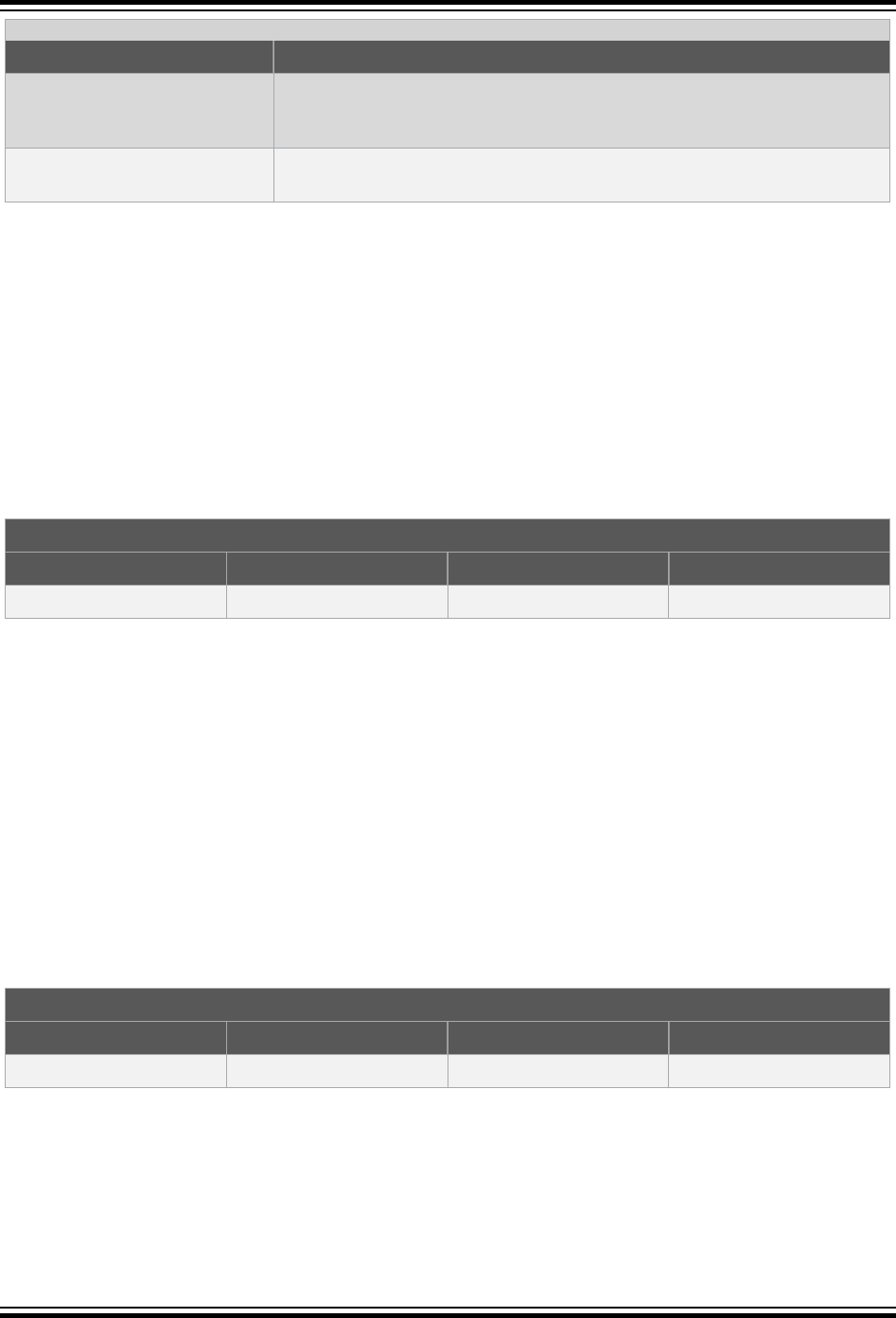
...........continued
Level Explanation
ignore The syntax is accepted in the specified compatibility mode, but the implied
action is not required or performed. The extension is ignored and a warning will
be issued by the compiler.
error The syntax is not accepted in the specified compatibility mode. An error will be
issued and compilation will be terminated.
Note that even if a C feature is supported by an MPLAB XC compiler, addresses, register names, assembly
instructions, or any other device-specific argument is unlikely to be valid when compiling for a Microchip device.
Always review code which uses these items in conjunction with the data sheet of your target Microchip device.
22.3 Data Type
Some compilers allow use of the boolean type, bool, as well as associated values true and false, as specified by
the C99 ANSI Standard. This type and these values may be used by all MPLAB XC compilers when in compatibility
mode (see note), as shown in the table below.
As indicated by the ANSI Standard, the <stdbool.h> header must be included for this feature to work as expected
when it is used with MPLAB XC compilers.
Table 22-3. Support for C99 Bool Type
IAR Compatibility Mode
Type XC8 XC16 XC32
bool
support support support
Do not confuse the boolean type, bool, and the integer type, bit, implemented by MPLAB XC8.
Note: Not all C99 features have been adopted by all Microchip MPLAB XC compilers.
22.4 Operator
The @ operator may be used with other compilers to indicate the desired memory location of an object. As Table A-4
indicates, support for this syntax in MPLAB C is limited to MPLAB XC8 only.
Any address specified with another device is unlikely to be correct on a new architecture. Review the address in
conjunction with the data sheet for your target Microchip device.
Using @ in a compatibility mode with MPLAB XC8 will work correctly, but will generate a warning. To prevent this
warning from appearing again, use the reviewed address with the MPLAB C __at() specifier instead.
For MPLAB XC16/32, consider using the address attribute.
Table 22-4. Support for Non-Standard Operator
IAR Compatibility Mode
Operator XC8 XC16 XC32
@
native support error error
22.5 Extended Keywords
Non-standard extensions often specify how objects are defined or accessed. Keywords are usually used to indicate
the feature. The non-standard C keywords corresponding to other compilers are listed in the following table, as well
as the level of compatibility offered by MPLAB XC compilers. The table notes offer more information about
extensions.
XC32 Compiler for PIC32M
Embedded Compiler Compatibility Mode
© 2020 Microchip Technology Inc.
User Guide
DS50002799B-page 211
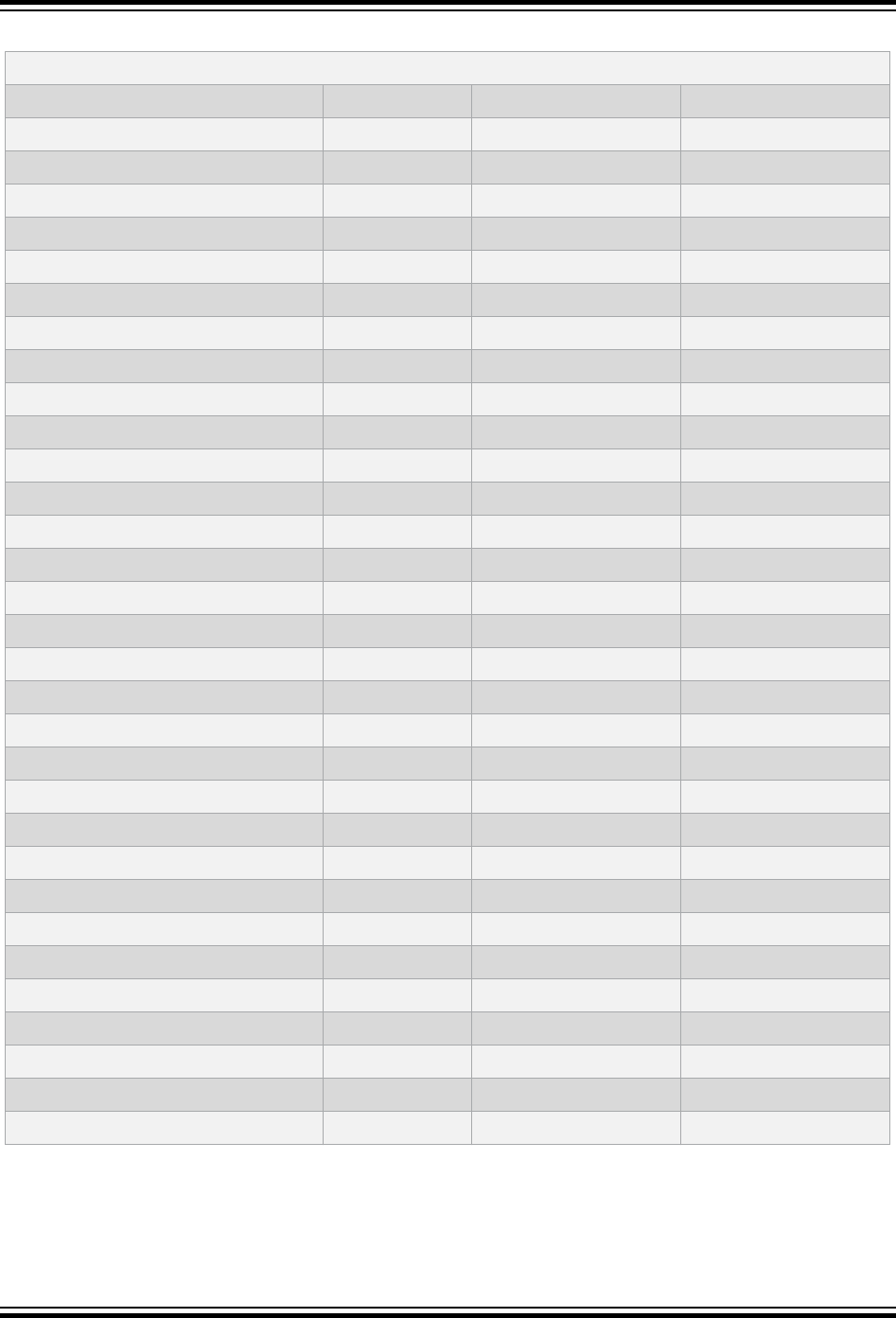
Table 22-5. Support for Non-Standard Keywords
IAR Compatibility Mode
Keyword XC8 XC16 XC32
__section_begin
ignore support support
__section_end
ignore support support
__section_size
ignore support support
__segment_begin
ignore support support
__segment_end
ignore support support
__segment_size
ignore support support
__sfb
ignore support support
__sfe
ignore support support
__sfs
ignore support support
__asm or asm
(1)
support
(2)
native support native support
__arm
ignore ignore ignore
__big_endian
error error error
__fiq
support error error
__intrinsic
ignore ignore ignore
__interwork
ignore ignore ignore
__irq
support error error
__little_endian
(3)
ignore ignore ignore
__nested
ignore ignore ignore
__no_init
support support support
__noreturn
ignore support support
__ramfunc
ignore ignore support
(4)
__packed
ignore
(5)
support support
__root
ignore support support
__swi
ignore ignore ignore
__task
ignore support support
__weak
ignore support support
__thumb
ignore ignore ignore
__farfunc
ignore ignore ignore
__huge
ignore ignore ignore
__nearfunc
ignore ignore ignore
__inline
support native support native support
XC32 Compiler for PIC32M
Embedded Compiler Compatibility Mode
© 2020 Microchip Technology Inc.
User Guide
DS50002799B-page 212
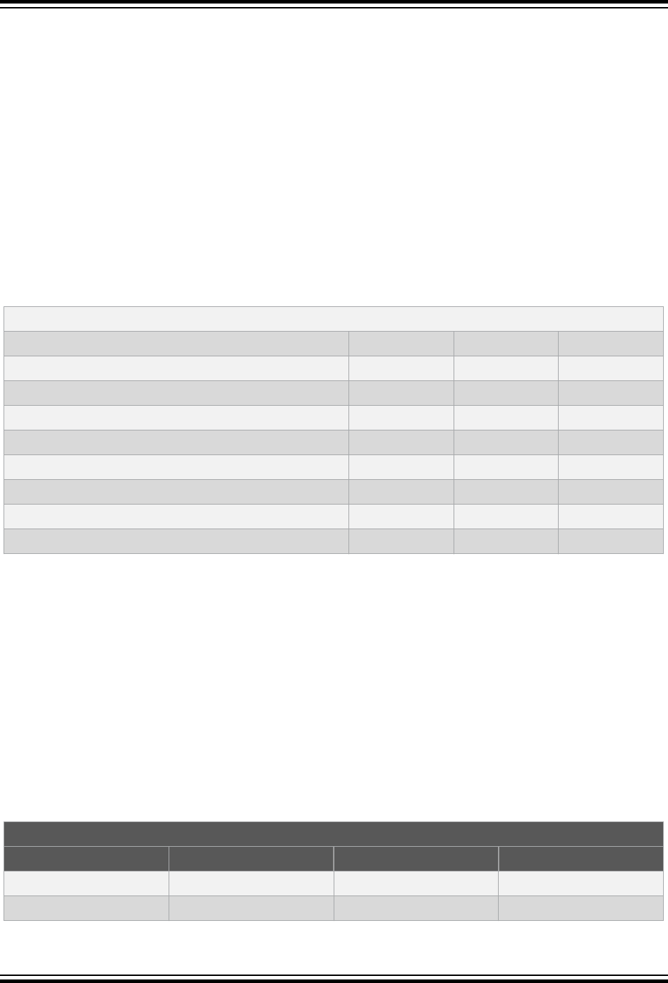
Note:
1. All assembly code specified by this construct is device-specific and will need review when porting to any
Microchip device.
2. The keyword, asm, is supported natively by MPLAB XC8, but this compiler only supports the __asm keyword
in IAR compatibility mode.
3. This is the default (and only) endianism used by all MPLAB XC compilers.
4. When used with MPLAB XC32, this must be used with the __longcall__ macro for full compatibility.
5. Although this keyword is ignored, by default, all structures are packed when using MPLAB XC8, so there is no
loss of functionality.
22.6 Intrinsic Functions
Intrinsic functions can be used to perform common tasks in the source code. The MPLAB XC compilers’ support for
the intrinsic functions offered by other compilers is shown in the following table.
Table 22-6. Support for Non-Standard Intrinsic Functions
IAR Compatibility Mode
Function XC8 XC16 XC32
__disable_fiq
(1)
support ignore ignore
__disable_interrupt
support support support
__disable_irq
(1)
support ignore ignore
__enable_fiq
(1)
support ignore ignore
__enable_interrupt
support support support
__enable_irq
(1)
support ignore ignore
__get_interrupt_state
ignore support support
__set_interrupt_state
ignore support support
Note: 1. These intrinsic functions map to macros which disable or enable the global interrupt enable bit on 8-bit
PIC
®
devices.
The header file <xc.h> must be included for supported functions to operate correctly.
22.7 Pragmas
Pragmas may be used by a compiler to control code generation. Any compiler will ignore an unknown pragma, but
many pragmas implemented by another compiler have also been implemented by the MPLAB XC compilers in
compatibility mode. The table below shows the pragmas and the level of support when using each of the MPLAB XC
compilers.
Many of these pragmas take arguments. Even if a pragma is supported by an MPLAB XC compiler, this support may
not apply to all of the pragma’s arguments. This is indicated in the table.
Table 22-7. Support for Non-Standard Pragmas
IAR Compatibility Mode
Pragma XC8 XC16 XC32
bitfields
ignore ignore ignore
data_alignment
ignore support support
XC32 Compiler for PIC32M
Embedded Compiler Compatibility Mode
© 2020 Microchip Technology Inc.
User Guide
DS50002799B-page 213
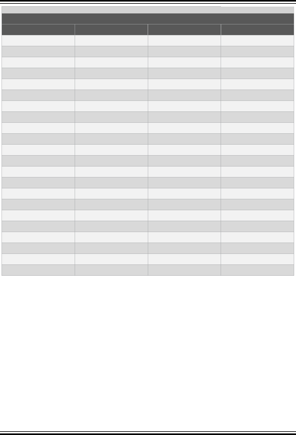
...........continued
IAR Compatibility Mode
Pragma XC8 XC16 XC32
diag_default
ignore ignore ignore
diag_error
ignore ignore ignore
diag_remark
ignore ignore ignore
diag_suppress
ignore ignore ignore
diag_warning
ignore ignore ignore
include_alias
ignore ignore ignore
inline
support (no args) support (no args) support (no args)
language
ignore ignore ignore
location
ignore support support
message
support native support native support
object_attribute
ignore ignore ignore
optimize
ignore native support native support
pack
ignore native support native support
__printf_args
support support support
required
ignore support support
rtmodel
ignore ignore ignore
__scanf__args
ignore support support
section
ignore support support
segment
ignore support support
swi_number
ignore ignore ignore
type_attribute
ignore ignore ignore
weak
ignore native support native support
XC32 Compiler for PIC32M
Embedded Compiler Compatibility Mode
© 2020 Microchip Technology Inc.
User Guide
DS50002799B-page 214

23. Implementation-Defined Behavior
This section discusses the choices for implementation defined behavior in compiler.
23.1 Overview
ISO C requires a conforming implementation to document the choices for behaviors defined in the standard as
“implementation-defined.” The following sections list all such areas, the choices made for the compiler, and the
corresponding section number from the ISO/IEC 9899:1999 standard.
23.2 Translation
ISO Standard: “How a diagnostic is identified (3.10, 5.1.1.3).”
Implementation: All output to stderr is a diagnostic.
ISO Standard: “Whether each nonempty sequence of white-space characters other than new-
line is retained or replaced by one space character in translation phase 3
(5.1.1.2).”
Implementation: Each sequence of whitespace is replaced by a single character.
23.3 Environment
ISO Standard: “The name and type of the function called at program start-up in a freestanding
environment (5.1.2.1).”
Implementation:
int main (void);
ISO Standard: “The effect of program termination in a freestanding environment (5.1.2.1).”
Implementation: An infinite loop (branch to self) instruction will be executed.
ISO Standard: “An alternative manner in which the main function may be defined (5.1.2.2.1).”
Implementation:
int main (void);
ISO Standard: “The values given to the strings pointed to by the argv argument to main
(5.1.2.2.1).”
Implementation: No arguments are passed to main. Reference to argc or argv is undefined.
ISO Standard: “What constitutes an interactive device (5.1.2.3).”
Implementation: Application defined.
ISO Standard: “Signals for which the equivalent of signal(sig, SIG_IGN); is executed
at program start-up (7.14.1.1).”
Implementation: Signals are application defined.
ISO Standard: “The form of the status returned to the host environment to indicate
unsuccessful termination when the SIGABRT signal is raised and not caught
(7.20.4.1).”
Implementation: The host environment is application defined.
ISO Standard: “The forms of the status returned to the host environment by the exit function
to report successful and unsuccessful termination (7.20.4.3).”
Implementation: The host environment is application defined.
XC32 Compiler for PIC32M
Implementation-Defined Behavior
© 2020 Microchip Technology Inc.
User Guide
DS50002799B-page 215

ISO Standard: “The status returned to the host environment by the exit function if the value of
its argument is other than zero, EXIT_SUCCESS, or EXIT_FAILURE
(7.20.4.3).”
Implementation: The host environment is application defined.
ISO Standard: “The set of environment names and the method for altering the environment list
used by the getenv function (7.20.4.4).”
Implementation: The host environment is application defined.
ISO Standard: “The manner of execution of the string by the system function (7.20.4.5).”
Implementation: The host environment is application defined.
23.4 Identifiers
ISO Standard: “Which additional multibyte characters may appear in identifiers and their
correspondence to universal character names (6.4.2).”
Implementation: No.
ISO Standard: “The number of significant initial characters in an identifier (5.2.4.1, 6.4.2).”
Implementation: All characters are significant.
23.5 Characters
ISO Standard: “The number of bits in a byte (C90 3.4, C99 3.6).”
Implementation: 8.
ISO Standard: “The values of the members of the execution character set (C90 and C99
5.2.1).”
ISO Standard: “The unique value of the member of the execution character set produced for
each of the standard alphabetic escape sequences (C90 and C99 5.2.2).”
Implementation: The execution character set is ASCII.
ISO Standard: “The value of a char object into which has been stored any character other
than a member of the basic execution character set (C90 6.1.2.5, C99 6.2.5).”
Implementation: The value of the char object is the 8-bit binary representation of the character
in the source character set. That is, no translation is done.
ISO Standard: “Which of signed char or unsigned char has the same range, representation,
and behavior as “plain” char (C90 6.1.2.5, C90 6.2.1.1, C99 6.2.5, C99
6.3.1.1).”
Implementation: By default on PIC32M, signed char is functionally equivalent to plain char.
ISO Standard: “The mapping of members of the source character set (in character constants
and string literals) to members of the execution character set (C90 6.1.3.4, C99
6.4.4.4, C90 and C99 5.1.1.2).”
Implementation: The binary representation of the source character set is preserved to the
execution character set.
ISO Standard: “The value of an integer character constant containing more than one
character or containing a character or escape sequence that does not map to a
single-byte execution character (C90 6.1.3.4, C99 6.4.4.4).”
XC32 Compiler for PIC32M
Implementation-Defined Behavior
© 2020 Microchip Technology Inc.
User Guide
DS50002799B-page 216

Implementation: The compiler determines the value for a multi-character character constant one
character at a time. The previous value is shifted left by eight, and the bit
pattern of the next character is masked in. The final result is of type int. If the
result is larger than can be represented by an int, a warning diagnostic is
issued and the value truncated to int size.
ISO Standard: “The value of a wide character constant containing more than one multibyte
character, or containing a multibyte character or escape sequence not
represented in the extended execution character set (C90 6.1.3.4, C99
6.4.4.4).”
Implementation: See previous.
ISO Standard: “The current locale used to convert a wide character constant consisting of a
single multibyte character that maps to a member of the extended execution
character set into a corresponding wide character code (C90 6.1.3.4, C99
6.4.4.4).”
Implementation: LC_ALL
ISO Standard: “The current locale used to convert a wide string literal into corresponding wide
character codes (C90 6.1.4, C99 6.4.5).”
Implementation: LC_ALL
ISO Standard: “The value of a string literal containing a multibyte character or escape
sequence not represented in the execution character set (C90 6.1.4, C99
6.4.5).”
Implementation: The binary representation of the characters is preserved from the source
character set.
23.6 Integers
ISO Standard: “Any extended integer types that exist in the implementation (C99 6.2.5).”
Implementation: There are no extended integer types.
ISO Standard: “Whether signed integer types are represented using sign and magnitude,
two’s complement, or one’s complement and whether the extraordinary value is
a trap representation or an ordinary value (C99 6.2.6.2).”
Implementation: All integer types are represented as two’s complement, and all bit patterns are
ordinary values.
23.7 Floating-Point
ISO Standard: “The accuracy of the floating-point operations and of the library functions in
<math.h> and <complex.h> that return floating-point results (C90 and C99
5.2.4.2.2).”
Implementation: The accuracy is unknown.
ISO Standard: “The accuracy of the conversions between floating-point internal
representations and string representations performed by the library functions in
<stdio.h>, <stdlib.h>, and <wchar.h> (C90 and C99 5.2.4.2.2).”
Implementation: The accuracy is unknown.
ISO Standard: “The rounding behaviors characterized by non-standard values of
FLT_ROUNDS (C90 and C99 5.2.4.2.2).”
XC32 Compiler for PIC32M
Implementation-Defined Behavior
© 2020 Microchip Technology Inc.
User Guide
DS50002799B-page 217

Implementation: No such values are used.
ISO Standard: “The evaluation methods characterized by non-standard negative values of
FLT_EVAL_METHOD (C90 and C99 5.2.4.2.2).”
Implementation: No such values are used.
ISO Standard: “The direction of rounding when an integer is converted to a floating-point
number that cannot exactly represent the original value (C90 6.2.1.3, C99
6.3.1.4).”
Implementation: C99 Annex F is followed.
ISO Standard: “The direction of rounding when a floating-point number is converted to a
narrower floating-point number (C90 6.2.1.4, 6.3.1.5).”
Implementation: C99 Annex F is followed.
ISO Standard: “How the nearest representable value or the larger or smaller representable
value immediately adjacent to the nearest representable value is chosen for
certain floating constants (C90 6.1.3.1, C99 6.4.4.2).”
Implementation: C99 Annex F is followed.
ISO Standard: “Whether and how floating expressions are contracted when not disallowed by
the FP_CONTRACT pragma (C99 6.5).”
Implementation: The pragma is not implemented.
ISO Standard: “The default state for the FENV_ACCESS pragma (C99 7.6.1).”
Implementation: This pragma is not implemented.
ISO Standard: “Additional floating-point exceptions, rounding modes, environments, and
classifications, and their macro names (C99 7.6, 7.12).”
Implementation: None supported.
ISO Standard: “The default state for the FP_CONTRACT pragma (C99 7.12.2).”
Implementation: This pragma is not implemented.
ISO Standard: “Whether the “inexact” floating-point exception can be raised when the rounded
result actually does equal the mathematical result in an IEC 60559 conformant
implementation (C99 F.9).”
Implementation: Unknown.
ISO Standard: “Whether the “underflow” (and “inexact”) floating-point exception can be raised
when a result is tiny but not inexact in an IEC 60559 conformant
implementation (C99 F.9).”
Implementation: Unknown.
23.8 Arrays and Pointers
ISO Standard: “The result of converting a pointer to an integer or vice versa (C90 6.3.4, C99
6.3.2.3).”
XC32 Compiler for PIC32M
Implementation-Defined Behavior
© 2020 Microchip Technology Inc.
User Guide
DS50002799B-page 218

Implementation: A cast from an integer to a pointer or vice versa results uses the binary
representation of the source type, reinterpreted as appropriate for the
destination type. If the source type is larger than the destination type, the Most
Significant bits are discarded. When casting from a pointer to an integer, if the
source type is smaller than the destination type, the result is sign extended.
When casting from an integer to a pointer, if the source type is smaller than the
destination type, the result is extended based on the signedness of the source
type.
ISO Standard: “The size of the result of subtracting two pointers to elements of the same array
(C90 6.3.6, C99 6.5.6).”
Implementation: 32-bit signed integer.
23.9 Hints
ISO Standard: “The extent to which suggestions made by using the register storage-class
specifier are effective (C90 6.5.1, C99 6.7.1).”
Implementation: The register storage class specifier generally has no effect.
ISO Standard: “The extent to which suggestions made by using the inline function specifier are
effective (C99 6.7.4).”
Implementation: If -fno-inline or -O0 are specified, no functions will be inlined, even if
specified with the inline specifier. Otherwise, the function may or may not be
inlined dependent on the optimization heuristics of the compiler.
23.10 Structures, Unions, Enumerations, and Bit Fields
ISO Standard: “A member of a union object is accessed using a member of a different type
(C90 6.3.2.3).”
Implementation: The corresponding bytes of the union object are interpreted as an object of the
type of the member being accessed without regard for alignment or other
possible invalid conditions.
ISO Standard: “Whether a “plain” int bit field is treated as a signed int bit field or as an
unsigned int bit field (C90 6.5.2, C90 6.5.2.1, C99 6.7.2, C99 6.7.2.1).”
Implementation: By default on PIC32M, a plain int bit field is treated as a signed integer. This
behavior can be altered by use of the -funsigned-bitfields command
line option.
ISO Standard: “Allowable bit field types other than _Bool, signed int, and unsigned
int (C99 6.7.2.1).”
Implementation: No other types are supported.
ISO Standard: “Whether a bit field can straddle a storage unit boundary (C90 6.5.2.1, C99
6.7.2.1).”
Implementation: No.
ISO Standard: “The order of allocation of bit fields within a unit (C90 6.5.2.1, C99 6.7.2.1).”
Implementation: Bit fields are allocated left to right.
ISO Standard: “The alignment of non-bit field members of structures (C90 6.5.2.1, C99
6.7.2.1).”
XC32 Compiler for PIC32M
Implementation-Defined Behavior
© 2020 Microchip Technology Inc.
User Guide
DS50002799B-page 219

Implementation: Each member is located to the lowest available offset allowable according to
the alignment restrictions of the member type.
ISO Standard: “The integer type compatible with each enumerated type (C90 6.5.2.2, C99
6.7.2.2).”
Implementation: If the enumeration values are all non-negative, the type is unsigned int,
else it is int. The -fshort-enums command line option can change this.
23.11 Qualifiers
ISO Standard: “What constitutes an access to an object that has volatile-qualified type (C90
6.5.3, C99 6.7.3).”
Implementation: Any expression which uses the value of or stores a value to a volatile object is
considered an access to that object. There is no guarantee that such an
access is atomic.If an expression contains a reference to a volatile object but
neither uses the value nor stores to the object, the expression is considered an
access to the volatile object or not depending on the type of the object. If the
object is of scalar type, an aggregate type with a single member of scalar type,
or a union with members of (only) scalar type, the expression is considered an
access to the volatile object. Otherwise, the expression is evaluated for its side
effects but is not considered an access to the volatile object. For example:
volatile int a;
a; /* access to ‘a’ since ‘a’ is scalar */
23.12 Declarators
ISO Standard: “The maximum number of declarators that may modify an arithmetic, structure
or union type (C90 6.5.4).”
Implementation: No limit.
23.13 Statements
ISO Standard: “The maximum number of case values in a switch statement (C90 6.6.4.2).”
Implementation: No limit.
23.14 Pre-Processing Directives
ISO Standard: “How sequences in both forms of header names are mapped to headers or
external source file names (C90 6.1.7, C99 6.4.7).”
Implementation: The character sequence between the delimiters is considered to be a string
which is a file name for the host environment.
ISO Standard: “Whether the value of a character constant in a constant expression that
controls conditional inclusion matches the value of the same character
constant in the execution character set (C90 6.8.1, C99 6.10.1).”
Implementation: Yes.
XC32 Compiler for PIC32M
Implementation-Defined Behavior
© 2020 Microchip Technology Inc.
User Guide
DS50002799B-page 220

ISO Standard: “Whether the value of a single-character character constant in a constant
expression that controls conditional inclusion may have a negative value (C90
6.8.1, C99 6.10.1).”
Implementation: Yes.
ISO Standard: “The places that are searched for an included < > delimited header, and how
the places are specified or the header is identified (C90 6.8.2, C99 6.10.2).”
Implementation:
<install directory>/lib/gcc/pic32mx/3.4.4/include<install
directory>/pic32mx/include
ISO Standard: “How the named source file is searched for in an included "" delimited header
(C90 6.8.2, C99 6.10.2).”
Implementation: The compiler first searches for the named file in the directory containing the
including file, the directories specified by the -iquote command line option (if
any), then the directories which are searched for a < > delimited header.
ISO Standard: “The method by which preprocessing tokens are combined into a header name
(C90 6.8.2, C99 6.10.2).”
Implementation: All tokens, including whitespace, are considered part of the header file name.
Macro expansion is not performed on tokens inside the delimiters.
ISO Standard: “The nesting limit for #include processing (C90 6.8.2, C99 6.10.2).”
Implementation: No limit.
ISO Standard: “The behavior on each recognized non-STDC #pragma directive (C90 6.8.6,
C99 6.10.6).”
Implementation: See 9.11 Variable Attributes.
ISO Standard: “The definitions for __DATE_ _ and __TIME_ _ when respectively, the date
and time of translation are not available (C90 6.8.8, C99 6.10.8).”
Implementation: The date and time of translation are always available.
23.15 Library Functions
ISO Standard: “The Null Pointer constant to which the macro NULL expands (C90 7.1.6, C99
7.17).”
Implementation:
(void *)0
ISO Standard: “Any library facilities available to a freestanding program, other than the
minimal set required by clause 4 (5.1.2.1).”
Implementation: See the 32-Bit Language Tools Libraries (DS51685).
ISO Standard: “The format of the diagnostic printed by the assert macro (7.2.1.1).”
Implementation: “Failed assertion ‘message’ at line line of ‘filename’.\n”
ISO Standard: “The default state for the FENV_ACCESS pragma (7.6.1).”
Implementation: Unimplemented.
ISO Standard: “The representation of floating-point exception flags stored by the
fegetexceptflag function (7.6.2.2).”
Implementation: Unimplemented.
ISO Standard: “Whether the feraiseexcept function raises the inexact exception in
addition to the overflow or underflow exception (7.6.2.3).”
XC32 Compiler for PIC32M
Implementation-Defined Behavior
© 2020 Microchip Technology Inc.
User Guide
DS50002799B-page 221

Implementation: Unimplemented.
ISO Standard: “Floating environment macros other than FE_DFL_ENV that can be used as the
argument to the fesetenv or feupdateenv function (7.6.4.3, 7.6.4.4).”
Implementation: Unimplemented.
ISO Standard: “Strings other than "C" and "" that may be passed as the second argument to
the setlocale function (7.11.1.1).”
Implementation: None.
ISO Standard: “The types defined for float_t and double_t when the value of the
FLT_EVAL_METHOD macro is less than 0 or greater than 2 (7.12).”
Implementation: Unimplemented.
ISO Standard: “The infinity to which the INFINITY macro expands, if any (7.12).”
Implementation: Unimplemented.
ISO Standard: “The quiet NaN to which the NAN macro expands, when it is defined (7.12).”
Implementation: Unimplemented.
ISO Standard: “Domain errors for the mathematics functions, other than those required by this
International Standard (7.12.1).”
Implementation: None.
ISO Standard: “The values returned by the mathematics functions, and whether errno is set
to the value of the macro EDOM, on domain errors (7.12.1).”
Implementation: errno is set to EDOM on domain errors.
ISO Standard: “Whether the mathematics functions set errno to the value of the macro
ERANGE on overflow and/or underflow range errors (7.12.1).”
Implementation: Yes.
ISO Standard: “The default state for the FP_CONTRACT pragma (7.12.2)
Implementation: Unimplemented.
ISO Standard: “Whether a domain error occurs or zero is returned when the fmod function
has a second argument of zero (7.12.10.1).”
Implementation: NaN is returned.
ISO Standard: “The base-2 logarithm of the modulus used by the remquo function in reducing
the quotient (7.12.10.3).”
Implementation: Unimplemented.
ISO Standard: “The set of signals, their semantics, and their default handling (7.14).”
Implementation: The default handling of signals is to always return failure. Actual signal
handling is application defined.
ISO Standard: “If the equivalent of signal(sig, SIG_DFL); is not executed prior to the
call of a signal handler, the blocking of the signal that is performed (7.14.1.1).”
Implementation: Application defined.
ISO Standard: “Whether the equivalent of signal(sig, SIG_DFL); is executed prior to the
call of a signal handler for the signal SIGILL (7.14.1.1).”
Implementation: Application defined.
XC32 Compiler for PIC32M
Implementation-Defined Behavior
© 2020 Microchip Technology Inc.
User Guide
DS50002799B-page 222

ISO Standard: “Signal values other than SIGFPE, SIGILL, and SIGSEGV that correspond to a
computational exception (7.14.1.1).”
Implementation: Application defined.
ISO Standard: “Whether the last line of a text stream requires a terminating new-line character
(7.19.2).”
Implementation: Yes.
ISO Standard: “Whether space characters that are written out to a text stream immediately
before a new-line character appear when read in (7.19.2).”
Implementation: Yes.
ISO Standard: “The number of null characters that may be appended to data written to a
binary stream (7.19.2).”
Implementation: No null characters are appended to a binary stream.
ISO Standard: “Whether the file position indicator of an append-mode stream is initially
positioned at the beginning or end of the file (7.19.3).”
Implementation: Application defined. The system level function open is called with the
O_APPEND flag.
ISO Standard: “Whether a write on a text stream causes the associated file to be truncated
beyond that point (7.19.3).”
Implementation: Application defined.
ISO Standard: “The characteristics of file buffering (7.19.3).”
ISO Standard: “Whether a zero-length file actually exists (7.19.3).”
Implementation: Application defined.
ISO Standard: “The rules for composing valid file names (7.19.3).”
Implementation: Application defined.
ISO Standard: “Whether the same file can be open multiple times (7.19.3).”
Implementation: Application defined.
ISO Standard: “The nature and choice of encodings used for multibyte characters in files
(7.19.3).”
Implementation: Encodings are the same for each file.
ISO Standard: “The effect of the remove function on an open file (7.19.4.1).”
Implementation: Application defined. The system function unlink is called.
ISO Standard: “The effect if a file with the new name exists prior to a call to the rename
function (7.19.4.2).”
Implementation: Application defined. The system function link is called to create the new file
name, then unlink is called to remove the old file name. Typically, link will
fail if the new file name already exists.
ISO Standard: “Whether an open temporary file is removed upon abnormal program
termination (7.19.4.3).”
Implementation: No.
ISO Standard: “What happens when the tmpnam function is called more than TMP_MAX times
(7.19.4.4).”
Implementation: Temporary names will wrap around and be reused.
XC32 Compiler for PIC32M
Implementation-Defined Behavior
© 2020 Microchip Technology Inc.
User Guide
DS50002799B-page 223

ISO Standard: “Which changes of mode are permitted (if any), and under what circumstances
(7.19.5.4).”
Implementation: The file is closed via the system level close function and re-opened with the
open function with the new mode. No additional restriction beyond those of the
application defined open and close functions are imposed.
ISO Standard: “The style used to print an infinity or NaN, and the meaning of the n-char-
sequence if that style is printed for a NaN (7.19.6.1, 7.24.2.1).”
Implementation: No char sequence is printed.NaN is printed as "NaN".Infinity is printed as "[-/
+]Inf".
ISO Standard: “The output for %p conversion in the fprintf or fwprintf function (7.19.6.1,
7.24.2.1).”
Implementation: Functionally equivalent to %x.
ISO Standard: “The interpretation of a - character that is neither the first nor the last
character, nor the second where a ^ character is the first, in the scanlist for %
[ conversion in the fscanf or fwscanf function (7.19.6.2, 7.24.2.1).”
Implementation: Unknown
ISO Standard: “The set of sequences matched by the %p conversion in the fscanf or
fwscanf function (7.19.6.2, 7.24.2.2).”
Implementation: The same set of sequences matched by %x.
ISO Standard: “The interpretation of the input item corresponding to a %p conversion in the
fscanf or fwscanf function (7.19.6.2, 7.24.2.2).”
Implementation: If the result is not a valid pointer, the behavior is undefined.
ISO Standard: “The value to which the macro errno is set by the fgetpos, fsetpos, or
ftell functions on failure (7.19.9.1, 7.19.9.3, 7.19.9.4).”
Implementation: If the result exceeds LONG_MAX, errno is set to ERANGE.Other errors are
application defined according to the application definition of the lseek
function.
ISO Standard: “The meaning of the n-char-sequence in a string converted by the strtod,
strtof, strtold, wcstod, wcstof, or wcstold function (7.20.1.3,
7.24.4.1.1).”
Implementation: No meaning is attached to the sequence.
ISO Standard: “Whether or not the strtod, strtof, strtold, wcstod, wcstof, or
wcstold function sets errno to ERANGE when underflow occurs (7.20.1.3,
7.24.4.1.1).”
Implementation: Yes.
ISO Standard: “Whether the calloc, malloc, and realloc functions return a Null Pointer
or a pointer to an allocated object when the size requested is zero (7.20.3).”
Implementation: A pointer to a statically allocated object is returned.
ISO Standard: “Whether open output streams are flushed, open streams are closed, or
temporary files are removed when the abort function is called (7.20.4.1).”
Implementation: No.
ISO Standard: “The termination status returned to the host environment by the abort function
(7.20.4.1).”
Implementation: By default, there is no host environment.
XC32 Compiler for PIC32M
Implementation-Defined Behavior
© 2020 Microchip Technology Inc.
User Guide
DS50002799B-page 224

ISO Standard: “The value returned by the system function when its argument is not a Null
Pointer (7.20.4.5).”
Implementation: Application defined.
ISO Standard: “The local time zone and Daylight Saving Time (7.23.1).”
Implementation: Application defined.
ISO Standard: “The era for the clock function (7.23.2.1).”
Implementation: Application defined.
ISO Standard: “The positive value for tm_isdst in a normalized tmx structure (7.23.2.6).”
Implementation: 1
ISO Standard: “The replacement string for the %Z specifier to the strftime, strfxtime,
wcsftime, and wcsfxtime functions in the “C” locale (7.23.3.5, 7.23.3.6,
7.24.5.1, 7.24.5.2).”
Implementation: Unimplemented.
ISO Standard: “Whether or when the trigonometric, hyperbolic, base-e exponential, base-e
logarithmic, error, and log gamma functions raise the inexact exception in an
IEC 60559 conformant implementation (F.9).”
Implementation: No.
ISO Standard: “Whether the inexact exception may be raised when the rounded result actually
does equal the mathematical result in an IEC 60559 conformant
implementation (F.9).”
Implementation: No.
ISO Standard: “Whether the underflow (and inexact) exception may be raised when a result is
tiny but not inexact in an IEC 60559 conformant implementation (F.9).”
Implementation: No.
ISO Standard: “Whether the functions honor the Rounding Direction mode (F.9).”
Implementation: The Rounding mode is not forced.
23.16 Architecture
ISO Standard: “The values or expressions assigned to the macros specified in the headers
<float.h>, <limits.h>, and <stdint.h> (C90 and C99 5.2.4.2, C99
7.18.2, 7.18.3).”
Implementation: See 9.3.2 limits.h.
ISO Standard: “The number, order, and encoding of bytes in any object (when not explicitly
specified in the standard) (C99 6.2.6.1).”
Implementation: Little endian, populated from Least Significant Byte first. See 9.2 Data
Representation.
ISO Standard: “The value of the result of the size of operator (C90 6.3.3.4, C99 6.5.3.4).”
Implementation: See 9.2 Data Representation.
XC32 Compiler for PIC32M
Implementation-Defined Behavior
© 2020 Microchip Technology Inc.
User Guide
DS50002799B-page 225

24. Deprecated Features
The features described below are considered to be obsolete and have been replaced with more advanced
functionality. Projects which depend on deprecated features will work properly with versions of the language tools
cited. The use of a deprecated feature will result in a warning; programmers are encouraged to revise their projects in
order to eliminate any dependency on deprecated features. Support for these features may be removed entirely in
future versions of the language tools.
24.1 Variables in Specified Registers
The compiler allows you to put a few global variables into specified hardware registers.
Note: Using too many registers may impair the ability of the 32-bit compiler to compile. It is not recommended that
registers be placed into fixed registers.
You can also specify the register in which an ordinary register variable should be allocate.
• Global register variables reserve registers throughout the program. This may be useful in programs such as
programming language interpreters which have a couple of global variables that are accessed very often.
• Local register variables in specific registers do not reserve the registers. The compiler’s data flow analysis is
capable of determining where the specified registers contain live values, and where they are available for other
uses. Stores into local register variables may be deleted when they appear to be unused. References to local
register variables may be deleted, moved or simplified.
These local variables are sometimes convenient for use with the extended inline assembly (see 18. Mixing C/C++
and Assembly Language), if you want to write one output of the assembler instruction directly into a particular
register. (This will work provided the register you specify fits the constraints specified for that operand in the inline
assembly statement).
24.2 Defining Global Register Variables
You can define a global register variable like this:
register int *foo asm ("t0");
Here t0 is the name of the register which should be used. Choose a register that is normally saved and restored by
function calls, so that library routines will not clobber it.
Defining a global register variable in a certain register reserves that register entirely for this use, at least within the
current compilation. The register will not be allocated for any other purpose in the functions in the current compilation.
The register will not be saved and restored by these functions. Stores into this register are never deleted even if they
would appear to be dead, but references may be deleted, moved or simplified.
It is not safe to access the global register variables from signal handlers, or from more than one thread of control,
because the system library routines may temporarily use the register for other things (unless you recompile them
especially for the task at hand).
It is not safe for one function that uses a global register variable to call another such function foo by way of a third
function lose that was compiled without knowledge of this variable (that is, in a source file in which the variable
wasn’t declared). This is because lose might save the register and put some other value there. For example, you
can’t expect a global register variable to be available in the comparison-function that you pass to qsort, since
qsort might have put something else in that register. This problem can be avoided by recompiling qsort with the
same global register variable definition.
If you want to recompile qsort or other source files that do not actually use your global register variable, so that they
will not use that register for any other purpose, then it suffices to specify the compiler command-line option -
ffixed-reg. You need not actually add a global register declaration to their source code.
A function that can alter the value of a global register variable cannot safely be called from a function compiled
without this variable, because it could clobber the value the caller expects to find there on return. Therefore, the
XC32 Compiler for PIC32M
Deprecated Features
© 2020 Microchip Technology Inc.
User Guide
DS50002799B-page 226

function that is the entry point into the part of the program that uses the global register variable must explicitly save
and restore the value that belongs to its caller.
The library function longjmp will restore to each global register variable the value it had at the time of the setjmp.
All global register variable declarations must precede all function definitions. If such a declaration appears after
function definitions, the register may be used for other purposes in the preceding functions.
Global register variables may not have initial values because an executable file has no means to supply initial
contents for a register.
24.3 Specifying Registers for Local Variables
You can define a local register variable with a specified register like this:
register int *foo asm ("t0");
Here t0 is the name of the register that should be used. Note that this is the same syntax used for defining global
register variables, but for a local variable it would appear within a function.
Defining such a register variable does not reserve the register; it remains available for other uses in places where
flow control determines the variable’s value is not live. Using this feature may leave the compiler too few available
registers to compile certain functions.
This option does not ensure that the compiler will generate code that has this variable in the register you specify at all
times. You may not code an explicit reference to this register in an asm statement and assume it will always refer to
this variable.
Assignments to local register variables may be deleted when they appear to be unused. References to local register
variables may be deleted, moved or simplified.
XC32 Compiler for PIC32M
Deprecated Features
© 2020 Microchip Technology Inc.
User Guide
DS50002799B-page 227

25. Built-In Functions
This appendix lists the built-in functions that are specific to MPLAB XC32 C/C++ Compiler.
Built-in functions give the C programmer access to assembler operators or machine instructions that are currently
only accessible using inline assembly, but are sufficiently useful that they are applicable to a broad range of
applications. Built-in functions are coded in C source files syntactically like function calls, but they are compiled to
assembly code that directly implements the function, and do not involve function calls or library routines.
There are a number of reasons why providing built-in functions is preferable to requiring programmers to use inline
assembly. They include the following:
Providing built-in functions for specific purposes simplifies coding.
Certain optimizations are disabled when inline assembly is used. This is not the case for built-in functions.
For machine instructions that use dedicated registers, coding inline assembly while avoiding register allocation errors
can require considerable care. The built-in functions make this process simpler as you do not need to be concerned
with the particular register requirements for each individual machine instruction.
XC32 Compiler for PIC32M
Built-In Functions
© 2020 Microchip Technology Inc.
User Guide
DS50002799B-page 228

26. Built-In Function Descriptions
This section describes the programmer interface to the compiler built-in functions. Since the functions are “built in”,
there are no header files associated with them. Similarly, there are no command-line switches associated with the
built-in functions – they are always available. The built-in function names are chosen such that they belong to the
compiler’s namespace (they all have the prefix _ _builtin_), so they will not -conflict with function or variable
names in the programmer’s namespace.
Built-In Function List
• __builtin_bcc0(rn,sel,clr)
• __builtin_bsc0(rn,sel,set)
• __builtin_bcsc0(rn,sel,clr,set)
• __builtin_clz(x)
• __builtin_ctz(x)
• __builtin_mips_cache(op,addr)
• __builtin_mxc0(rn,sel,val)
• __builtin_set_isr_state(unsigned int)
• __builtin_software_breakpoint(void)
• unsigned long__builtin_section_begin(quoted-section-name)
• unsigned long __builtin_section_end(quoted-section-name)
• unsigned long __builtin_section_size(quoted-section-name)
• unsigned int __builtin_get_isr_state(void)
26.1 __builtin_bcc0(rn,sel,clr)
Description
Clear the non-zero bits from CLR in CP0 register REG,SEL.
Prototype
unsigned int __builtin_bcc0(rn,sel,clr);
Argument
rn : cp0 register number
sel : cp0 select number
clr : 32-bit mask to clear
Return Value
unsigned int : new value
Assembler Operator/Machine Instruction
mfc0 t, cs
nor d, s, t
and d, s, j
mtc0 s, cd
Error Messages
None.
26.2 __builtin_bsc0(rn,sel,set)
Description
Set the non-zero bits from set in CP0 register rn,sel.
XC32 Compiler for PIC32M
Built-In Function Descriptions
© 2020 Microchip Technology Inc.
User Guide
DS50002799B-page 229

Prototype
unsigned int __builtin_bsc0(rn,sel,set);
Argument
rn : cp0 register number
sel : cp0 select number
set : 32-bit mask to set
Return Value
unsigned int : new value
Assembler Operator/ Machine Instruction
mfc0 t, cs
or d, s, t
mtc0 s, cd
Error Messages
None.
26.3 __builtin_bcsc0(rn,sel,clr,set)
Description
Clear the non-zero bits from CLR and set non-zero bits and set non-zero bits from set in CP0 register rn,sel.
Prototype
unsigned int __builtin_bcsc0(rn,sel,clr,set);
Argument
rn : cp0 register number
sel : cp0 select number
clr : 32-bit mask to clear
set : 32-bit mask to set
Return Value
unsigned int : new value
Assembler Operator/ Machine Instruction
mfc0 t, cs
nor d, s, t
and d, s, j
or d, s, t
mtc0 s, cd
Error Messages
None.
26.4 __builtin_clz(x)
Description
Count leading (high-order) zero bits in x considered as a 32-bit word.
Prototype
unsigned int __builtin_clz(x);
Argument
XC32 Compiler for PIC32M
Built-In Function Descriptions
© 2020 Microchip Technology Inc.
User Guide
DS50002799B-page 230

x : 32-bit word to count
Return Value
unsigned int : number of leading zero bits
Assembler Operator/ Machine Instruction
clz d, s
Error Messages
None.
26.5 __builtin_ctz(x)
Description
Count trailing (low-order) zero bits in x considered as a 32-bit word.
Prototype
unsigned int __builtin_ctz(x);
Argument
x : 32-bit word to count
Return Value
unsigned int : number of trailing zero bits
Assembler Operator/ Machine Instruction
subu d, s, t
and d, s, t
clz d, s
li d, j
subu d, s, j
Error Messages
None.
26.6 __builtin_mips_cache(op,addr)
Description
Perform an operation on a cache line indicated by address. See the PIC32 Family Reference Manual for valid
operation values.
Prototype
void __builtin_mips_cache(op,addr);
Argument
None.
Return Value
void
Assembler Operator/ Machine Instruction
cache op, addr
Error Message
None.
XC32 Compiler for PIC32M
Built-In Function Descriptions
© 2020 Microchip Technology Inc.
User Guide
DS50002799B-page 231

26.7 __builtin_mxc0(rn,sel,val)
Description
Exchange (Swap) val and CP0 register rn,sel.
Prototype
unsigned int __builtin_mxc0(rn,sel,val);
Argument
rn : cp0 register number
sel : cp0 select number
val : 32-bit value to move to the register
Return Value
unsigned int : previous value in specified CP0 register
Assembler Operator/ Machine Instruction
mfc0 t, cs
mtc0 s, cd
Error Messages
None.
26.8 __builtin_set_isr_state(unsigned int)
Description
Set the Interrupt Priority Level and Interrupt Enable bits using a value obtained from
__builtin_get_isr_state().
Prototype
void __builtin_set_isr_state(unsigned int);
Argument
An unsigned integer value obtained from __builtin_get_isr_state().
Return Value
None.
Assembler Operator/ Machine Instruction
di
ehb
mfc0 $2, $12, 0
ins $2,$3,10,3
srl $3,$3,3
ins $2,$3,0,1
mtc0 $2, $12, 0
ehb
Error Messages
None.
26.9 __builtin_software_breakpoint(void)
Description
Insert a software breakpoint.
XC32 Compiler for PIC32M
Built-In Function Descriptions
© 2020 Microchip Technology Inc.
User Guide
DS50002799B-page 232

Note that the __conditional_software_breakpoint() macro defined in assert.h provides a lightweight variant
of assert(exp) that causes only a software breakpoint when the assertion fails rather than printing a message.
This macro is disabled if, at the moment of including <assert.h>, a macro with the name NDEBUG has already been
defined of if a macro with the name __DEBUG has not been defined. For example:
__conditional_software_breakpoint(myPtr!=NULL);
Prototype
void__builtin_software_breakpoint(void)
Argument
None.
Return Value
None.
Assembler Operator/ Machine Instruction
sdbbp 0
Error Messages
None.
26.10 unsigned long__builtin_section_begin(quoted-section-name)
Remember: This builtin gets run-time information about section addresses and sizes.
Description
Return the beginning address of the quoted section name.
Prototype
unsigned long __builtin_section_begin(quoted-section-name);
Argument
quoted-section-name The name of the section.
Return Value
The address of the section.
Assembler Operator/ Machine Instruction
.startof.
Error Messages
An “undefined reference” error message will be displayed if the quoted section name does not exist in the link.
26.11 unsigned long __builtin_section_end(quoted-section-name)
Remember: This builtin gets run-time information about section addresses and sizes.
Description
XC32 Compiler for PIC32M
Built-In Function Descriptions
© 2020 Microchip Technology Inc.
User Guide
DS50002799B-page 233

Return the end address of the quoted section name + 1.
Prototype
unsigned long __builtin_section_end(quoted-section-name);
Argument
quoted-section-name The name of the section.
Return Value
The end address of the section + 1.
Assembler Operator/ Machine Instruction
.endof.
Error Messages
An “undefined reference” error message will be displayed if the quoted section name does not exist in the link.
26.12 unsigned long __builtin_section_size(quoted-section-name)
Remember: This builtin gets run-time information about section addresses and sizes.
Description
Return the size in bytes of the named quoted section.
Prototype
unsigned long __builtin_section_size(quoted-section-name);
Argument
quoted-section-name The name of the section.
Return Value
The size in bytes of the named section.
Assembler Operator/ Machine Instruction
.sizeof.
Error Messages
An “undefined reference” error message will be displayed if the quoted section name does not exist in the link.
26.13 unsigned int __builtin_get_isr_state(void)
Remember: This builtin inspects or manipulates the current CPU interrupt state.
Description
Get the current Interrupt Priority Level and Interrupt Enable bits.
Prototype
unsigned int __builtin_get_isr_state(void);
XC32 Compiler for PIC32M
Built-In Function Descriptions
© 2020 Microchip Technology Inc.
User Guide
DS50002799B-page 234

Argument
None.
Return Value
The current IPL and interrupt enable bits in a packed format. This value is to be used with the
__builtin_set_isr_state() function.
Assembler Operator/ Machine Instruction
mfc0 $3, $12, 0
srl $2,$3,10
ins $2,$3,3,1
andi $2,$2,0xf
sw $2,0($fp)
Error Messages
None.
XC32 Compiler for PIC32M
Built-In Function Descriptions
© 2020 Microchip Technology Inc.
User Guide
DS50002799B-page 235
27. Built-In DSP Functions
Many PIC32 MCUs support a DSP engine, including instructions that are designed to improve the performance of
DSP and media applications. The DSPr2 engine provides instructions that operate on packed 8-bit/16-bit integer
data, Q7, Q15 and Q31 fractional data.
The XC32 C compiler supports these DSP operations using both the generic vector extensions and a collection of
built-in functions. Both kinds of support are enabled automatically when you select a DSP device with the -
mprocessor option.
The SCOUNT and POS bits of the DSP control register are global. The WRDSP, EXTPDP, EXTPDPV and MTHLIP
instructions modify the SCOUNT and POS bits. During optimization, the compiler will not delete these instructions
and it will not delete calls to functions containing these instructions.
At present, the XC32 C compiler provides support for only operations on 32-bit vectors. The vector type associated
with 8-bit integer data is usually called v4i8, the vector type associated with Q7 is usually called v4q7, the vector type
associated with 16-bit integer data is usually called v2i16, and the vector type associated with Q15 is usually called
v2q15. They can be defined in C as follows:
typedef signed char v4i8 __attribute__ ((vector_size(4)));
typedef signed char v4q7 __attribute__ ((vector_size(4)));
typedef short v2i16 __attribute__ ((vector_size(4)));
typedef short v2q15 __attribute__ ((vector_size(4)));
The v4i8, v4q7, v2i16 and v2q15 values are initialized in the same way as aggregates. For example:
v4i8 a = {1, 2, 3, 4};
v4i8 b;
b = (v4i8) {5, 6, 7, 8};
v2q15 c = {0x0fcb, 0x3a75};
v2q15 d;
d = (v2q15) {0.1234 * 0x1.0p15, 0.4567 * 0x1.0p15};
Note:
1. The first value is the least significant and the last value is the most significant. The code above will set the
lowest byte of a to 1.
2. Q7, Q15 and Q31 values must be initialized with their integer representation. As shown in this example, the
integer representation of a Q7 value can be obtained by multiplying the fractional value by 0x1.0p7. The
equivalent for Q15 values is to multiply by 0x1.0p15. The equivalent for Q31 values is to multiply by 0x1.0p31.
The table below lists the v4i8 and v2q15 operations for which hardware support exists. The a and b are v4i8 values,
and c and d are v2q15 values.
C Code Instruction
a + b addu.qb
c + d addq.ph
a - b subu.qb
c - d subq.ph
The table below lists the v2i16 operation for which hardware support exists. The e and f are v2i16 values.
C Code Instruction
e * f mul.ph
It is easier to describe the DSP built-in functions if the types are defined beforehand.
typedef int q31;
typedef int i32;
XC32 Compiler for PIC32M
Built-In DSP Functions
© 2020 Microchip Technology Inc.
User Guide
DS50002799B-page 236
typedef unsigned int ui32;
typedef long long a64;
The q31 and i32 operations are actually the same as int, but q31 is used to indicate a Q31 fractional value and i32
to indicate a 32-bit integer value. Similarly, a64 is the same as long long, but a64 is used to indicate values that
will be placed in one of the four DSP accumulators ($ac0, $ac1, $ac2 or $ac3).
Also, some built-in functions prefer or require immediate numbers as parameters, because the corresponding DSP
instructions accept both immediate numbers and register operands, or accept immediate numbers only. The
immediate parameters are listed as follows.
imm0_3: 0 to 3.
imm0_7: 0 to 7.
imm0_15: 0 to 15.
imm0_31: 0 to 31.
imm0_63: 0 to 63.
imm0_255: 0 to 255.
imm_n32_31: -32 to 31.
imm_n512_511: -512 to 511.
The following built-in functions map directly to a particular DSP instruction. Please refer to the PIC32 DSP
documentation for details on what each instruction does. In the table below, the function provides a way to generate
the DSP instruction in your code. For example, in v2q15 __builtin_mips_addq_ph (v2q15, v2q15), the
addq_ph is the actual DSP instruction.
Table 27-1. Map Directly to DSP Instruction
v2q15 __builtin_mips_absq_s_ph (v2q15)
q31 __builtin_mips_absq_s_w (q31)
v2q15 __builtin_mips_addq_ph (v2q15, v2q15)
v2q15 __builtin_mips_addq_s_ph (v2q15, v2q15)
q31 __builtin_mips_addq_s_w (q31, q31)
i32 __builtin_mips_addsc (i32, i32)
v4i8 __builtin_mips_addu_qb (v4i8, v4i8)
v4i8 __builtin_mips_addu_s_qb (v4i8, v4i8)
i32 __builtin_mips_addwc (i32, i32)
i32 __builtin_mips_bitrev (i32)
i32 __builtin_mips_bposge32 (void)
void __builtin_mips_cmp_eq_ph (v2q15, v2q15)
void __builtin_mips_cmp_le_ph (v2q15, v2q15)
void __builtin_mips_cmp_lt_ph (v2q15, v2q15)
i32 __builtin_mips_cmpgu_eq_qb (v4i8, v4i8)
i32 __builtin_mips_cmpgu_le_qb (v4i8, v4i8)
i32 __builtin_mips_cmpgu_lt_qb (v4i8, v4i8)
void __builtin_mips_cmpu_eq_qb (v4i8, v4i8)
void __builtin_mips_cmpu_le_qb (v4i8, v4i8)
void __builtin_mips_cmpu_lt_qb (v4i8, v4i8)
a64 __builtin_mips_dpaq_s_w_ph (a64, v2q15, v2q15)
a64 __builtin_mips_dpaq_sa_l_w (a64, q31, q31)
XC32 Compiler for PIC32M
Built-In DSP Functions
© 2020 Microchip Technology Inc.
User Guide
DS50002799B-page 237
a64 __builtin_mips_dpau_h_qbl (a64, v4i8, v4i8)
a64 __builtin_mips_dpau_h_qbr (a64, v4i8, v4i8)
a64 __builtin_mips_dpsq_s_w_ph (a64, v2q15, v2q15)
a64 __builtin_mips_dpsq_sa_l_w (a64, q31, q31)
a64 __builtin_mips_dpsu_h_qbl (a64, v4i8, v4i8)
a64 __builtin_mips_dpsu_h_qbr (a64, v4i8, v4i8)
i32 __builtin_mips_extp (a64, i32)
i32 __builtin_mips_extp (a64, imm0_31)
i32 __builtin_mips_extpdp (a64, i32)
i32 __builtin_mips_extpdp (a64, imm0_31)
i32 __builtin_mips_extr_r_w (a64, i32)
i32 __builtin_mips_extr_r_w (a64, imm0_31)
i32 __builtin_mips_extr_rs_w (a64, i32)
i32 __builtin_mips_extr_rs_w (a64, imm0_31)
i32 __builtin_mips_extr_s_h (a64, i32)
i32 __builtin_mips_extr_s_h (a64, imm0_31)
i32 __builtin_mips_extr_w (a64, i32)
i32 __builtin_mips_extr_w (a64, imm0_31)
i32 __builtin_mips_insv (i32, i32)
i32 __builtin_mips_lbux (void *, i32)
i32 __builtin_mips_lhx (void *, i32)
i32 __builtin_mips_lwx (void *, i32)
a64 __builtin_mips_maq_s_w_phl (a64, v2q15, v2q15)
a64 __builtin_mips_maq_s_w_phr (a64, v2q15, v2q15)
a64 __builtin_mips_maq_sa_w_phl (a64, v2q15, v2q15)
a64 __builtin_mips_maq_sa_w_phr (a64, v2q15, v2q15)
i32 __builtin_mips_modsub (i32, i32)
a64 __builtin_mips_mthlip (a64, i32)
q31 __builtin_mips_muleq_s_w_phl (v2q15, v2q15)
q31 __builtin_mips_muleq_s_w_phr (v2q15, v2q15)
v2q15 __builtin_mips_muleu_s_ph_qbl (v4i8, v2q15)
v2q15 __builtin_mips_muleu_s_ph_qbr (v4i8, v2q15)
v2q15 __builtin_mips_mulq_rs_ph (v2q15, v2q15)
a64 __builtin_mips_mulsaq_s_w_ph (a64, v2q15, v2q15)
v2q15 __builtin_mips_packrl_ph (v2q15, v2q15)
v2q15 __builtin_mips_pick_ph (v2q15, v2q15)
v4i8 __builtin_mips_pick_qb (v4i8, v4i8)
XC32 Compiler for PIC32M
Built-In DSP Functions
© 2020 Microchip Technology Inc.
User Guide
DS50002799B-page 238
q31 __builtin_mips_preceq_w_phl (v2q15)
q31 __builtin_mips_preceq_w_phr (v2q15)
v2q15 __builtin_mips_precequ_ph_qbl (v4i8)
v2q15 __builtin_mips_precequ_ph_qbla (v4i8)
v2q15 __builtin_mips_precequ_ph_qbr (v4i8)
v2q15 __builtin_mips_precequ_ph_qbra (v4i8)
v2q15 __builtin_mips_preceu_ph_qbl (v4i8)
v2q15 __builtin_mips_preceu_ph_qbla (v4i8)
v2q15 __builtin_mips_preceu_ph_qbr (v4i8)
v2q15 __builtin_mips_preceu_ph_qbra (v4i8)
v2q15 __builtin_mips_precrq_ph_w (q31, q31)
v4i8 __builtin_mips_precrq_qb_ph (v2q15, v2q15)
v2q15 __builtin_mips_precrq_rs_ph_w (q31, q31)
v4i8 __builtin_mips_precrqu_s_qb_ph (v2q15, v2q15)
i32 __builtin_mips_raddu_w_qb (v4i8)
i32 __builtin_mips_rddsp (imm0_63)
v2q15 __builtin_mips_repl_ph (i32)
v2q15 __builtin_mips_repl_ph (imm_n512_511)
v4i8 __builtin_mips_repl_qb (i32)
v4i8 __builtin_mips_repl_qb (imm0_255)
a64 __builtin_mips_shilo (a64, i32)
a64 __builtin_mips_shilo (a64, imm_n32_31)
v2q15 __builtin_mips_shll_ph (v2q15, i32)
v2q15 __builtin_mips_shll_ph (v2q15, imm0_15)
v4i8 __builtin_mips_shll_qb (v4i8, i32)
v4i8 __builtin_mips_shll_qb (v4i8, imm0_7)
v2q15 __builtin_mips_shll_s_ph (v2q15, i32)
v2q15 __builtin_mips_shll_s_ph (v2q15, imm0_15)
q31 __builtin_mips_shll_s_w (q31, i32)
q31 __builtin_mips_shll_s_w (q31, imm0_31)
v2q15 __builtin_mips_shra_ph (v2q15, i32)
v2q15 __builtin_mips_shra_ph (v2q15, imm0_15)
v2q15 __builtin_mips_shra_r_ph (v2q15, i32)
v2q15 __builtin_mips_shra_r_ph (v2q15, imm0_15)
q31 __builtin_mips_shra_r_w (q31, i32)
q31 __builtin_mips_shra_r_w (q31, imm0_31)
v4i8 __builtin_mips_shrl_qb (v4i8, i32)
XC32 Compiler for PIC32M
Built-In DSP Functions
© 2020 Microchip Technology Inc.
User Guide
DS50002799B-page 239
v4i8 __builtin_mips_shrl_qb (v4i8, imm0_7)
v2q15 __builtin_mips_subq_ph (v2q15, v2q15)
v2q15 __builtin_mips_subq_s_ph (v2q15, v2q15)
q31 __builtin_mips_subq_s_w (q31, q31)
v4i8 __builtin_mips_subu_qb (v4i8, v4i8)
v4i8 __builtin_mips_subu_s_qb (v4i8, v4i8)
void __builtin_mips_wrdsp (i32, imm0_63)
The following built-in functions map directly to a particular MIPS DSP REV 2 instruction. Please refer to the PIC32
DSP documentation for details on what each instruction does.
Table 27-2. Map Directly to MIPS DSP Instruction
v4q7 __builtin_mips_absq_s_qb (v4q7);
v2q15 __builtin_mips_addqh_ph (v2q15, v2q15);
v2q15 __builtin_mips_addqh_r_ph (v2q15, v2q15);
q31 __builtin_mips_addqh_r_w (q31, q31);
q31 __builtin_mips_addqh_w (q31, q31);
v2i16 __builtin_mips_addu_ph (v2i16, v2i16);
v2i16 __builtin_mips_addu_s_ph (v2i16, v2i16);
v4i8 __builtin_mips_adduh_qb (v4i8, v4i8);
v4i8 __builtin_mips_adduh_r_qb (v4i8, v4i8);
i32 __builtin_mips_append (i32, i32, imm0_31);
i32 __builtin_mips_balign (i32, i32, imm0_3);
i32 __builtin_mips_cmpgdu_eq_qb (v4i8, v4i8);
i32 __builtin_mips_cmpgdu_le_qb (v4i8, v4i8);
i32 __builtin_mips_cmpgdu_lt_qb (v4i8, v4i8);
a64 __builtin_mips_dpa_w_ph (a64, v2i16, v2i16);
a64 __builtin_mips_dpaqx_s_w_ph (a64, v2q15, v2q15);
a64 __builtin_mips_dpaqx_sa_w_ph (a64, v2q15, v2q15);
a64 __builtin_mips_dpax_w_ph (a64, v2i16, v2i16);
a64 __builtin_mips_dps_w_ph (a64, v2i16, v2i16);
a64 __builtin_mips_dpsqx_s_w_ph (a64, v2q15, v2q15);
a64 __builtin_mips_dpsqx_sa_w_ph (a64, v2q15, v2q15);
a64 __builtin_mips_dpsx_w_ph (a64, v2i16, v2i16);
a64 __builtin_mips_madd (a64, i32, i32);
a64 __builtin_mips_maddu (a64, ui32, ui32);
a64 __builtin_mips_msub (a64, i32, i32);
a64 __builtin_mips_msubu (a64, ui32, ui32);
XC32 Compiler for PIC32M
Built-In DSP Functions
© 2020 Microchip Technology Inc.
User Guide
DS50002799B-page 240
v2i16 __builtin_mips_mul_ph (v2i16, v2i16);
v2i16 __builtin_mips_mul_s_ph (v2i16, v2i16);
q31 __builtin_mips_mulq_rs_w (q31, q31);
v2q15 __builtin_mips_mulq_s_ph (v2q15, v2q15);
q31 __builtin_mips_mulq_s_w (q31, q31);
a64 __builtin_mips_mulsa_w_ph (a64, v2i16, v2i16);
a64 __builtin_mips_mult (i32, i32);
a64 __builtin_mips_multu (ui32, ui32);
v4i8 __builtin_mips_precr_qb_ph (v2i16, v2i16);
v2i16 __builtin_mips_precr_sra_ph_w (i32, i32, imm0_31);
v2i16 __builtin_mips_precr_sra_r_ph_w (i32, i32, imm0_31);
i32 __builtin_mips_prepend (i32, i32, imm0_31);
v4i8 __builtin_mips_shra_qb (v4i8, i32);
v4i8 __builtin_mips_shra_qb (v4i8, imm0_7);
v4i8 __builtin_mips_shra_r_qb (v4i8, i32);
v4i8 __builtin_mips_shra_r_qb (v4i8, imm0_7);
v2i16 __builtin_mips_shrl_ph (v2i16, i32);
v2i16 __builtin_mips_shrl_ph (v2i16, imm0_15);
v2q15 __builtin_mips_subqh_ph (v2q15, v2q15);
v2q15 __builtin_mips_subqh_r_ph (v2q15, v2q15);
q31 __builtin_mips_subqh_r_w (q31, q31);
q31 __builtin_mips_subqh_w (q31, q31);
v2i16 __builtin_mips_subu_ph (v2i16, v2i16);
v2i16 __builtin_mips_subu_s_ph (v2i16, v2i16);
v4i8 __builtin_mips_subuh_qb (v4i8, v4i8);
v4i8 __builtin_mips_subuh_r_qb (v4i8, v4i8);
XC32 Compiler for PIC32M
Built-In DSP Functions
© 2020 Microchip Technology Inc.
User Guide
DS50002799B-page 241
28. ASCII Character Set
Table 28-1. ASCII Character Set
Most Significant Character
Least Significant Character Hex 0 1 2 3 4 5 6 7
0 NUL DLE Space 0 @ P ‘ p
1 SOH DC1 ! 1 A Q a q
2 STX DC2 " 2 B R b r
3 ETX DC3 # 3 C S c s
4 EOT DC4 $ 4 D T d t
5 ENQ NAK % 5 E U e u
6 ACK SYN & 6 F V f v
7 Bell ETB ’ 7 G W g w
8 BS CAN ( 8 H X h x
9 HT EM ) 9 I Y i y
A LF SUB * : J Z j z
B VT ESC + ; K [ k {
C FF FS , < L \ l |
D CR GS - = M ] m }
E SO RS . > N ^ n ~
F SI US / ? O _ o DEL
XC32 Compiler for PIC32M
ASCII Character Set
© 2020 Microchip Technology Inc.
User Guide
DS50002799B-page 242

29. Document Revision History
Revision A (August 2018)
Initial revision of the document.
Revision B (April 2020)
• The document was re-formatted throughout, including paragraph numbering and minor editing changes.
• Added new topic 4.5.20 How Do I Stop My Project's Checksum From Changing? to the How To’s section.
• Corrected description of option -fenforce-eh-specs in Table 5-7.
• Revised 6. Command-line Driver section extensively.
• Updated Example 10-6 and Example 10-7 in 10.6.3 Using an Application-Defined Memory Region.
• Added examples for keep and noload in the 14.2.1 Function Attributes.
• Adding more information to 16.2.2 Jump to NMI Handler (_nmi_handler) if an NMI Occurred.
XC32 Compiler for PIC32M
Document Revision History
© 2020 Microchip Technology Inc.
User Guide
DS50002799B-page 243

The Microchip Website
Microchip provides online support via our website at http://www.microchip.com/. This website is used to make files
and information easily available to customers. Some of the content available includes:
• Product Support – Data sheets and errata, application notes and sample programs, design resources, user’s
guides and hardware support documents, latest software releases and archived software
• General Technical Support – Frequently Asked Questions (FAQs), technical support requests, online
discussion groups, Microchip design partner program member listing
• Business of Microchip – Product selector and ordering guides, latest Microchip press releases, listing of
seminars and events, listings of Microchip sales offices, distributors and factory representatives
Product Change Notification Service
Microchip’s product change notification service helps keep customers current on Microchip products. Subscribers will
receive email notification whenever there are changes, updates, revisions or errata related to a specified product
family or development tool of interest.
To register, go to http://www.microchip.com/pcn and follow the registration instructions.
Customer Support
Users of Microchip products can receive assistance through several channels:
• Distributor or Representative
• Local Sales Office
• Embedded Solutions Engineer (ESE)
• Technical Support
Customers should contact their distributor, representative or ESE for support. Local sales offices are also available to
help customers. A listing of sales offices and locations is included in this document.
Technical support is available through the web site at: http://www.microchip.com/support
Microchip Devices Code Protection Feature
Note the following details of the code protection feature on Microchip devices:
• Microchip products meet the specification contained in their particular Microchip Data Sheet.
• Microchip believes that its family of products is one of the most secure families of its kind on the market today,
when used in the intended manner and under normal conditions.
• There are dishonest and possibly illegal methods used to breach the code protection feature. All of these
methods, to our knowledge, require using the Microchip products in a manner outside the operating
specifications contained in Microchip’s Data Sheets. Most likely, the person doing so is engaged in theft of
intellectual property.
• Microchip is willing to work with the customer who is concerned about the integrity of their code.
• Neither Microchip nor any other semiconductor manufacturer can guarantee the security of their code. Code
protection does not mean that we are guaranteeing the product as “unbreakable.”
Code protection is constantly evolving. We at Microchip are committed to continuously improving the code protection
features of our products. Attempts to break Microchip’s code protection feature may be a violation of the Digital
Millennium Copyright Act. If such acts allow unauthorized access to your software or other copyrighted work, you
may have a right to sue for relief under that Act.
Legal Notice
Information contained in this publication regarding device applications and the like is provided only for your
convenience and may be superseded by updates. It is your responsibility to ensure that your application meets with
XC32 Compiler for PIC32M
© 2020 Microchip Technology Inc.
User Guide
DS50002799B-page 244

your specifications. MICROCHIP MAKES NO REPRESENTATIONS OR WARRANTIES OF ANY KIND WHETHER
EXPRESS OR IMPLIED, WRITTEN OR ORAL, STATUTORY OR OTHERWISE, RELATED TO THE INFORMATION,
INCLUDING BUT NOT LIMITED TO ITS CONDITION, QUALITY, PERFORMANCE, MERCHANTABILITY OR
FITNESS FOR PURPOSE. Microchip disclaims all liability arising from this information and its use. Use of Microchip
devices in life support and/or safety applications is entirely at the buyer’s risk, and the buyer agrees to defend,
indemnify and hold harmless Microchip from any and all damages, claims, suits, or expenses resulting from such
use. No licenses are conveyed, implicitly or otherwise, under any Microchip intellectual property rights unless
otherwise stated.
Trademarks
The Microchip name and logo, the Microchip logo, Adaptec, AnyRate, AVR, AVR logo, AVR Freaks, BesTime,
BitCloud, chipKIT, chipKIT logo, CryptoMemory, CryptoRF, dsPIC, FlashFlex, flexPWR, HELDO, IGLOO, JukeBlox,
KeeLoq, Kleer, LANCheck, LinkMD, maXStylus, maXTouch, MediaLB, megaAVR, Microsemi, Microsemi logo, MOST,
MOST logo, MPLAB, OptoLyzer, PackeTime, PIC, picoPower, PICSTART, PIC32 logo, PolarFire, Prochip Designer,
QTouch, SAM-BA, SenGenuity, SpyNIC, SST, SST Logo, SuperFlash, Symmetricom, SyncServer, Tachyon,
TempTrackr, TimeSource, tinyAVR, UNI/O, Vectron, and XMEGA are registered trademarks of Microchip Technology
Incorporated in the U.S.A. and other countries.
APT, ClockWorks, The Embedded Control Solutions Company, EtherSynch, FlashTec, Hyper Speed Control,
HyperLight Load, IntelliMOS, Libero, motorBench, mTouch, Powermite 3, Precision Edge, ProASIC, ProASIC Plus,
ProASIC Plus logo, Quiet-Wire, SmartFusion, SyncWorld, Temux, TimeCesium, TimeHub, TimePictra, TimeProvider,
Vite, WinPath, and ZL are registered trademarks of Microchip Technology Incorporated in the U.S.A.
Adjacent Key Suppression, AKS, Analog-for-the-Digital Age, Any Capacitor, AnyIn, AnyOut, BlueSky, BodyCom,
CodeGuard, CryptoAuthentication, CryptoAutomotive, CryptoCompanion, CryptoController, dsPICDEM,
dsPICDEM.net, Dynamic Average Matching, DAM, ECAN, EtherGREEN, In-Circuit Serial Programming, ICSP,
INICnet, Inter-Chip Connectivity, JitterBlocker, KleerNet, KleerNet logo, memBrain, Mindi, MiWi, MPASM, MPF,
MPLAB Certified logo, MPLIB, MPLINK, MultiTRAK, NetDetach, Omniscient Code Generation, PICDEM,
PICDEM.net, PICkit, PICtail, PowerSmart, PureSilicon, QMatrix, REAL ICE, Ripple Blocker, SAM-ICE, Serial Quad
I/O, SMART-I.S., SQI, SuperSwitcher, SuperSwitcher II, Total Endurance, TSHARC, USBCheck, VariSense,
ViewSpan, WiperLock, Wireless DNA, and ZENA are trademarks of Microchip Technology Incorporated in the U.S.A.
and other countries.
SQTP is a service mark of Microchip Technology Incorporated in the U.S.A.
The Adaptec logo, Frequency on Demand, Silicon Storage Technology, and Symmcom are registered trademarks of
Microchip Technology Inc. in other countries.
GestIC is a registered trademark of Microchip Technology Germany II GmbH & Co. KG, a subsidiary of Microchip
Technology Inc., in other countries.
All other trademarks mentioned herein are property of their respective companies.
©
2020, Microchip Technology Incorporated, Printed in the U.S.A., All Rights Reserved.
ISBN: 978-1-5224-6006-0
Quality Management System
For information regarding Microchip’s Quality Management Systems, please visit http://www.microchip.com/quality.
XC32 Compiler for PIC32M
© 2020 Microchip Technology Inc.
User Guide
DS50002799B-page 245
AMERICAS ASIA/PACIFIC ASIA/PACIFIC EUROPE
Corporate Office
2355 West Chandler Blvd.
Chandler, AZ 85224-6199
Tel: 480-792-7200
Fax: 480-792-7277
Technical Support:
http://www.microchip.com/support
Web Address:
http://www.microchip.com
Atlanta
Duluth, GA
Tel: 678-957-9614
Fax: 678-957-1455
Austin, TX
Tel: 512-257-3370
Boston
Westborough, MA
Tel: 774-760-0087
Fax: 774-760-0088
Chicago
Itasca, IL
Tel: 630-285-0071
Fax: 630-285-0075
Dallas
Addison, TX
Tel: 972-818-7423
Fax: 972-818-2924
Detroit
Novi, MI
Tel: 248-848-4000
Houston, TX
Tel: 281-894-5983
Indianapolis
Noblesville, IN
Tel: 317-773-8323
Fax: 317-773-5453
Tel: 317-536-2380
Los Angeles
Mission Viejo, CA
Tel: 949-462-9523
Fax: 949-462-9608
Tel: 951-273-7800
Raleigh, NC
Tel: 919-844-7510
New York, NY
Tel: 631-435-6000
San Jose, CA
Tel: 408-735-9110
Tel: 408-436-4270
Canada - Toronto
Tel: 905-695-1980
Fax: 905-695-2078
Australia - Sydney
Tel: 61-2-9868-6733
China - Beijing
Tel: 86-10-8569-7000
China - Chengdu
Tel: 86-28-8665-5511
China - Chongqing
Tel: 86-23-8980-9588
China - Dongguan
Tel: 86-769-8702-9880
China - Guangzhou
Tel: 86-20-8755-8029
China - Hangzhou
Tel: 86-571-8792-8115
China - Hong Kong SAR
Tel: 852-2943-5100
China - Nanjing
Tel: 86-25-8473-2460
China - Qingdao
Tel: 86-532-8502-7355
China - Shanghai
Tel: 86-21-3326-8000
China - Shenyang
Tel: 86-24-2334-2829
China - Shenzhen
Tel: 86-755-8864-2200
China - Suzhou
Tel: 86-186-6233-1526
China - Wuhan
Tel: 86-27-5980-5300
China - Xian
Tel: 86-29-8833-7252
China - Xiamen
Tel: 86-592-2388138
China - Zhuhai
Tel: 86-756-3210040
India - Bangalore
Tel: 91-80-3090-4444
India - New Delhi
Tel: 91-11-4160-8631
India - Pune
Tel: 91-20-4121-0141
Japan - Osaka
Tel: 81-6-6152-7160
Japan - Tokyo
Tel: 81-3-6880- 3770
Korea - Daegu
Tel: 82-53-744-4301
Korea - Seoul
Tel: 82-2-554-7200
Malaysia - Kuala Lumpur
Tel: 60-3-7651-7906
Malaysia - Penang
Tel: 60-4-227-8870
Philippines - Manila
Tel: 63-2-634-9065
Singapore
Tel: 65-6334-8870
Taiwan - Hsin Chu
Tel: 886-3-577-8366
Taiwan - Kaohsiung
Tel: 886-7-213-7830
Taiwan - Taipei
Tel: 886-2-2508-8600
Thailand - Bangkok
Tel: 66-2-694-1351
Vietnam - Ho Chi Minh
Tel: 84-28-5448-2100
Austria - Wels
Tel: 43-7242-2244-39
Fax: 43-7242-2244-393
Denmark - Copenhagen
Tel: 45-4450-2828
Fax: 45-4485-2829
Finland - Espoo
Tel: 358-9-4520-820
France - Paris
Tel: 33-1-69-53-63-20
Fax: 33-1-69-30-90-79
Germany - Garching
Tel: 49-8931-9700
Germany - Haan
Tel: 49-2129-3766400
Germany - Heilbronn
Tel: 49-7131-72400
Germany - Karlsruhe
Tel: 49-721-625370
Germany - Munich
Tel: 49-89-627-144-0
Fax: 49-89-627-144-44
Germany - Rosenheim
Tel: 49-8031-354-560
Israel - Ra’anana
Tel: 972-9-744-7705
Italy - Milan
Tel: 39-0331-742611
Fax: 39-0331-466781
Italy - Padova
Tel: 39-049-7625286
Netherlands - Drunen
Tel: 31-416-690399
Fax: 31-416-690340
Norway - Trondheim
Tel: 47-72884388
Poland - Warsaw
Tel: 48-22-3325737
Romania - Bucharest
Tel: 40-21-407-87-50
Spain - Madrid
Tel: 34-91-708-08-90
Fax: 34-91-708-08-91
Sweden - Gothenberg
Tel: 46-31-704-60-40
Sweden - Stockholm
Tel: 46-8-5090-4654
UK - Wokingham
Tel: 44-118-921-5800
Fax: 44-118-921-5820
Worldwide Sales and Service
© 2020 Microchip Technology Inc.
User Guide
DS50002799B-page 246
